WARNING: Laser beams will cause eye damage. Do not look into bores of optical modules
or optical bers without eye protection.
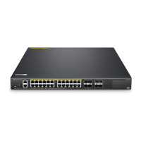
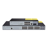
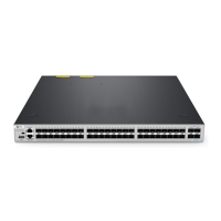
Connecting the RJ45 Ports
1. Connect an Ethernet cable to the RJ45 port of IP cameras, IP telephone, Access Points (AP), or other
network devices.
2. Connect the other end of the Ethernet cable to the RJ45 port of the switch.
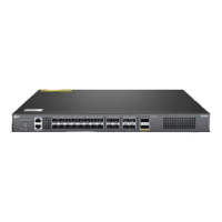
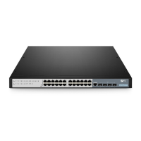
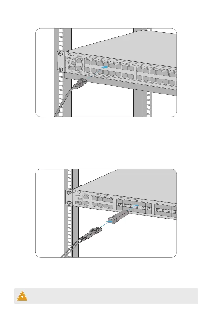
1. Plug the compatible SFP/SFP+ transceiver into the SFP/SFP+ port.
2. Connect a ber optic cable to the ber transceiver. Then connect the other end of the cable to
another ber device.
Connecting the SFP/SFP+ Ports
MINI CONSOLE
STATUSPWR1 PWR2
MGMT
SFP+
COMBO
21
43
65
87
21
43
65
87
109
1211
1413
1615
1817
2019
2221
2423
2625
2827
3029
31
On=Link Flashing=ACT Green=1000M Yellow=10/100M
MGMT
CONSOLE
 Loading...