Curtis-Toledo Rotary Compressor CAP862
Operations and Maintenance Manual
Chapter 4 Page 1
Chapter 4
System flow chart and components function
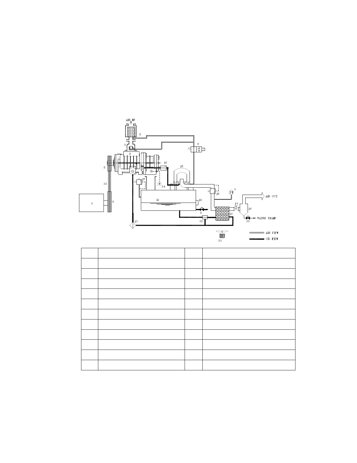
A. System flow chart and components function
SE20-50 System Flow Chart
1 Air intake filter 13 Oil filter
2 Motor 14 Air outlet ball valve
3 Intake valve 15 Oil separator
4 2-way solenoid valve 16 Oil level gauge
5 Pulley air end side 17 Pressure relief valve
6 Pulley motor side 18 Minimum pressure valve
7 Pressure transmitter 19 Water separator (optional)
8 Air end 20 Drain valve
9 Drain valve 21 Thermostatic valve
10 Oil return check valve 22 Belt
11 Separator tank 23 Fan
12 Radiator 24 Thermocouple