Curtis-Toledo Rotary Compressor CAP862
Operations and Maintenance Manual
Chapter 3 Page 1
Chapter 3 General Description
COMPRESSOR
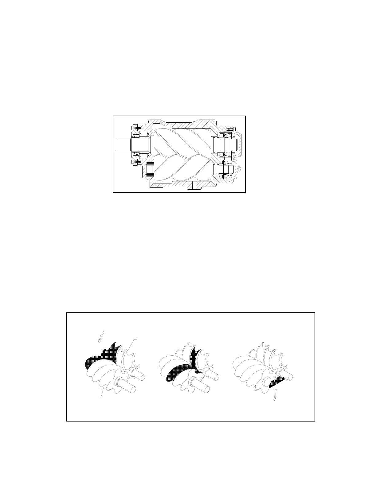
The compressor assembly is an oil flooded positive displacement, single stage, helical screw
type unit consisting of two rotors or screws supported axially by roller bearings and enclosed
in a housing or stator as depicted in the sectional view Figure 3-1.
Figure 3-1
Compressor Assembly
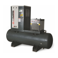
In operation as depicted below in the compression cycle (Ref. Figure 2-2), air entering the
compressor through the inlet port becomes trapped between the helical lobes of the main rotor and
the matching grooves of the secondary rotor (A). As the rotors turn air is trapped in the cavity
created by the mashing lobe and groove and reduced in volume or “compressed”. It is then pushed
through the successive cavities (B) until it reaches the discharge end of the compressor (C) and is
sent to the oil separator.
During the compressor cycle, oil is injected into the compressor for the purpose of dissipating the
heat of compression and to seal the internal clearances. The compressed air laden with oil leaves
the compressor through the discharge port and enters a reservoir where the oil and air are
separated. This process delivers a smooth flow of compressed air at the desired pressure.
Figure 2-2
Compression Cycle
INLET
DISCHARGE
MAIN ROTOR
SECONDARY
ROTOR
A B C