4
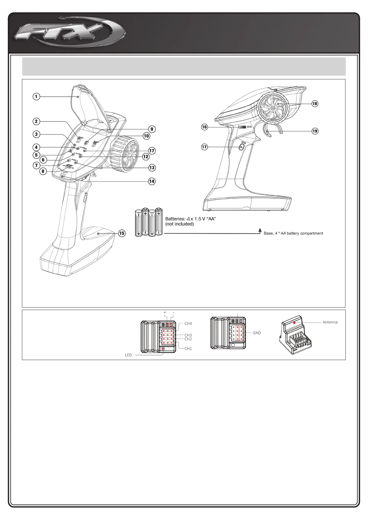
GETTING TO KNOW YOUR TRANSMITTER
Battery installation
1. Open the battery compartment cover.
2. Insert 4 fully-charged AA batteries into the compartment. Make
sure that the battery makes good contact with the battery com-
partment’s contacts and that they are inserted with the correct
polarity.
3. Replace battery compartment cover.
NOTE:
The transmitter features a low battery alarm: When the battery is
lower than 4.2v, the G.LED on the panel will ash slowly.
Binding
To ensure the best signal quality make sure that the receiver is
mounted in such a way that the antenna is in the upright, vertical
position.
The transmitter and receiver have already been bound at the factory.
1. Turn on the transmitter while holding the bind button to enter
bind mode. G.LED will start ashing quickly . Once in bind mode
release the bind button.
2. The receiver will enter bind mode automatically when powered on.
3. Once binding is successful the receiver’s LED will ash slowly
and the transmitter’s LED will remain solid after being rebooted.
NOTE:
When binding, put the transmitter into bind mode rst, then the
receiver.
Stick Calibration
This function is used to set the neutral position for throttle and
steering.
Every transmitter is calibrated before leaving the factory, however if
recalibration is required, please follow these steps:
1. Turn and hold the wheel as far clockwise as it will turn, push
the throttle trigger all the way forward, then turn on the transmit-
ter in calibration mode.
• The R.LED and G.LED will ash twice.
2. Calibrate steering: Turn the wheel completely clockwise, then
completely counter-clockwise.
• When calibration is complete the R.LED will turn o.
3. Trigger calibration: Pull the trigger back then forward as far as it
will go.
• When calibration is complete the G.LED will turn o.
4. Once calibration is complete press the bind key to save and
exit.
1 - Cover Panel
2 - Steering Reverse Switch (ST.REV)
3 - Power indicator LED (R. LED)
4 - Steering Trim (ST.TRIM-)
5 - Status indicator green LED (G.LED)
6 - Throttle Trim (TH.TRIM-)
7 - Steering D/R (ST.D / R-)
8 - Power Switch
9 - Bind Button (BIND)
10 - Throttle Reverse (TH.REV)
11 - Steering Trim (ST.TRIM +)
To ensure the best signal quality make
sure that the receiver is mounted in such
a way that the antenna is in the upright,
vertical position.
12 - Throttle Trim (TH.TRIM +)
13 - Steering D/R (ST.D / R +)
14 - Lanyard Eye
15 - Base, 4 x AA battery compartment
16 - Three-position switch (CH3)
17 - Button (CH4)
18 - Wheel Angle, the maximum rotation of the steering
wheel is 35 degrees from center to left or right (CH1)
19 - Throttle trigger, has a total throw of 12 degrees, 12.5
degrees forward and 12.5 degrees backward (CH2)
Receiver Overview