Maintenance Section 5-9
MAINTENANCE
FB42 08/01
© 2004 Alamo Group Inc.
MAINTENANCE
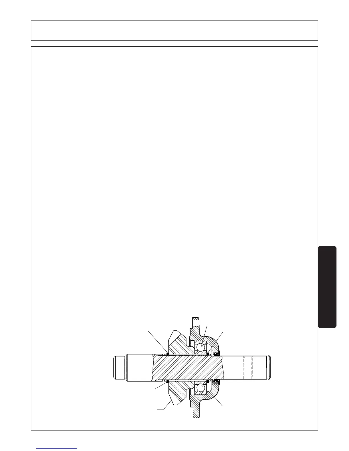
INPUT SHAFT (Figure 9)
DISASSEMBLY AND ASSEMBLY
1. Remove snap ring (Ref. #11) and then remove bearing housing (Ref. #13) by holding end of shaft which does
not have a cross hole or splines and tap opposite end of shaft on solid surface. Shock force will remove housing
from bearing (Ref.#4).
2. Remove snap ring (Ref. #7) closest to bearing. Tap end of shaft as explained in Step 1 until bearing and gear
drop off shaft.
3. Worn components can now be replaced and assembled in reverse order.
ASSEMBLY ORDER
1A. Install gear onto shaft as shown in Figure 9. Note location of two snap ring grooves.
2A. Install bearing on shaft.
NOTE: Use tube with ID just large enough to go over shaft to drive bearing against gear. Install snap ring (Ref
7).
3A. Press oil seal flush with front side of bearing housing (See SEAL INSTALLATION RECOMMENDATION).
4A. Lubricate ID of seal and insert shaft until bearing contacts housing. Press bearing into housing by hitting
end of shaft. Once bearing is in place insert snap ring (Ref #11). NOTE: Snap ring must be inserted between
bearing and gear before pressing bearing into housing.
SEAL INSTALLATION RECOMMENDATIONS
1. Check Seal - for damage that may have occurred prior to installation. A sealing lip that is turned back, cut or
otherwise damaged should be replaced.
2. Check Bore - to see that leading edge is deburred. A rounded corner or chamber should be provided.
3. Check Shaft - remove surface nicks, burrs and grooves and lubricate with a hard, fibrous grease. NOTE:
Wrap plastic tape around irregular shaft surfaces such as splines to protect seal during assembly.
4. Use Correct Installation Tool - Always use pipe or tube with approximate same OD as seal and press seal by
striking tube.
NEVER HAMMER DIRECTLY ON THE SURFACE OF THE SEAL.
FIGURE 9
4
13
11
22 TEETH - 1.47 RATIO
7
SNAP RING LOCATION