2-16
2-4 Serial Connector
Communication (RS-232C, RS-422/485) with a controller is enabled via the serial connector (CN1).
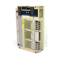
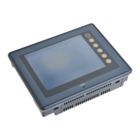
• For NP5M0101-5H4/4H4
NP5N0011-5H4/4H4
Bottom view Bottom view
The serial connector pins correspond to signals as given below.
CN1 (D-sub 9-pin, female)
Pin No.
RS-232C (Note: 1) RS-422 / RS-485 (Note: 1)
Signal Contents Signal Contents
1
NC
Not used +RD Receive data (+)
2
RD
Receive data -RD Receive data (-)
3
SD
Send data -SD Send data (-)
4
NC
Not used +SD Send data (+)
5
SG
Signal ground SG Signal ground
6
NC
Not used +RTS Request to send (+)
7
RTS
Request to send -RTS Request to send (-)
8
CTS
Clear to send NC Not used
9
NC
Not used +5V Use prohibited (Note: 2)
Note: 1) The signal level can be changed between RS-232C and RS-422/485 on the configuration software.
When RS-232C is selected, set the dip switches 5 and 7 to the OFF position.
(For more information on the dip switch, refer to “Chapter 2-6”.)
Note: 2) When RS-422/485 is selected, +5V is output from pin No. 9.
+5V is used as the power supply for the external terminating resistance for RS-422/485 communication.
It cannot be used as an external power supply.
Recommended connector
The following connector is recommended for a self-made cable.
Recommended
connector
DDK's 17JE-23090-02 (D8C) -CG D-sub 9-pin / male / inch screw thread (#4-40UNC) type /
with hood / lead- and cadmium-free
15
69
• For NP5M0101-3H4
NP5N0011-3H4

 Loading...

