Do you have a question about the Fuji Electric NA0AX06-PT and is the answer not in the manual?
Covers warnings and cautions for safe operation and handling of the device.
Lists the different models of SPF series analog and temperature measurement units.
Describes key features like connectable units and parameter setting functions.
Details required software versions for program loaders and main units.
Covers operating environment, mechanical, and electrical specifications.
Details functional and performance characteristics of the analog input unit.
Explains A/D conversion characteristics for analog input signals.
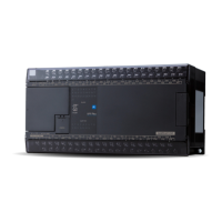
Identifies components and functions of the NA0AX06-MR analog input unit.
Provides wiring instructions for analog input units.
Provides dimensional drawings for specific expansion units.
Outlines memory addresses for analog input and output values.
Guides on connecting and registering analog units within the system.
Guides setting resolution and moving average for analog input units.
Provides instructions for removing the unit's upper cover.
Shows the circuit isolation block diagram for the analog input unit.
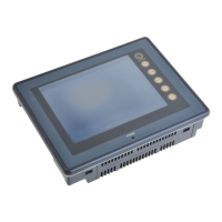
| Touch Panel | Yes |
|---|---|
| Communication Interface | RS-232 |
| Supply Voltage | 24 V DC |
| Operating Temperature | 0 to 50°C |
| Storage Temperature | -20 to 60°C |
