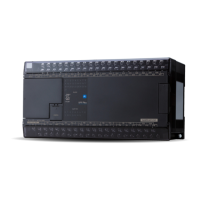
2-3-3 Analog input/output unit (Type: NA0AW06-MR)
(1) Names
The jumper pins in the analog input/output unit are used to change the analog signal range and digital value range. Therefore,
remove the upper cover and control board when setting the jumper pin.
NA0AW06-MR
3) JP1
JP1
D/A
A/D
B
U
B
U
B
U
10V
5V
I
V
CH0
CH1
4) JPA
6) JP3
6) JP4
U
B
5V
10V
I
V
CH0
CH1
5) JPB
7) JP5 (CH0) to JP8 (CH3)
10V
5V
B
U
1) Status indication LED
Nameplate
Expansion connector (IN)
Expansion connector (OUT)
2) Terminal block
Pin layout of control board
(When the upper cover is removed)
Pin layout of I/O board
(When the control board is removed)
<Notes on mounting/removing the upper cover and control board>
• When handling the analog unit, remove it from the control panel, turn off the power, and disconnect other units.
• The procedure for handling the upper cover and printed circuit board, see “Appendix 1 Unit Handling Procedure.”
• Before mounting/removing the upper cover or handling the printed circuit board, be sure to eliminate static electricity.

 Loading...
