Fuji Electric Corp. of America
47520 Westinghouse Drive, Fremont, CA 94539
Phone: 510-440-1060
www.americas.fujielectric.com
4. I_O (I/O Check)
4_00 I/O Signals on the Control Card Terminals
4_01 I/O Signals on the Control Card Terminals
under Communications.
4_02 Input Voltage on Terminal 12
4_03 Input Current on Terminal C1
4_04 Output Voltage on Terminal FMV
4_05 Output Voltage on Terminal FM2
4_06 Output Frequency on Terminal FMP
4_07 Input Voltage on Terminal C1
4_08 Output Current on Terminal FMI
4_09 Output Current on Terminal FM2
4_2
4 Cutomizable Logic Timer
1.F _ _
1.E _ _
1.C _ _
1.P _ _
1.H _ _
1.H1 _ _
1.A _ _
1.J _ _
1.J1 _ _
1.d _ _
1.U _ _
1.U1 _ _
1.Y _ _
1.k _ _
2. rEP
3. oEP
4. I_O
5. CHE
6. AL
5. CHE (Maintenacne Info)
5_00 Accumulated Run Time
5_01 DC Link Bus Voltage
5_03 Max Temperature of Heat Sink
5_04 Max Effectice Current
5_07 Accumulated Run Time of Cooling Fan
5_08 Number of Starts (Drive)
5_09 Input Watt-Hour
5_10 Input Watt-Hour Data
5_05 Capacitance of the DC Link Bus
Capacitance
5_06 Accumutated Run Time of Electolytic
Capacitors on the PCB
6. AL (Alarm Info)
6_00 Output Frequency
6_01 Output Current
6_02 Output Voltage
6_03 Calculated Torque
6_04 Reference Frequency
6_05 Rotational Ditection
6_06 Running Status
6_07 Accumulated Running Time
6_08 Number of Startups
6_09 DC Link Bus Voltage
6_10 Temperature Inside the Inverter
6_11 Max. Temperature of Heat Sink
6_12
Terminal I/O Status
6_13 Terminal Input Signal Status in HEX
6_14 Terminal Output Status in Hex
6_15
Number of Consecutice Occurrces
6_16 Overlapping Alarm 1
6_17 Overlapping Alarm 2
6_18 Communication Terminal Status I/0
6_19 Communication Terminal Status Input
6_20 Communication Terminal Status Output
6_21 Sub-Code
6_22 Running Status 2
6_23 Detected Speed
6_24 Running Status 3
6_25 Multiple Alarm Sub-Code
Quick Start Menus
1.F Fundamental Functions
1.E Extension Terminal Functions
1.C Control Functions of Frequency
1.P Motor 1 Parameters
1.H High Performance Functions
1.H1 High Performance Functions
1.A Motor 2 Functions
1.J Application Functions
1.J1 PID Functions
1.d Application Functions 2
1.U Customizable Logic
1.U1 Customizable Logic
1.Y Link Functions
1.k Keypad Functions
2. rEP (Data Check)
Displays function codes that
have been changed from
factory default
3. oPE (Operations Monitor)
3_00 Output frequency Before Slip
3_01 Output frequency After Slip
3_02 Output Current
3_03 Output Voltage
3_04 Calculated Torque
3_05 Reference Frequency
3_06 Rotation Direction
3_07 Running Status
3_08 Motor Speed r/min
3_09 Load Shaft speed
3_10 PID SV
3_11 PID PV
3_12 Torque Limit Value A
3_13 Torque Limit Value B
3_14 Ratio Setting
3_15 Line Speed r/min
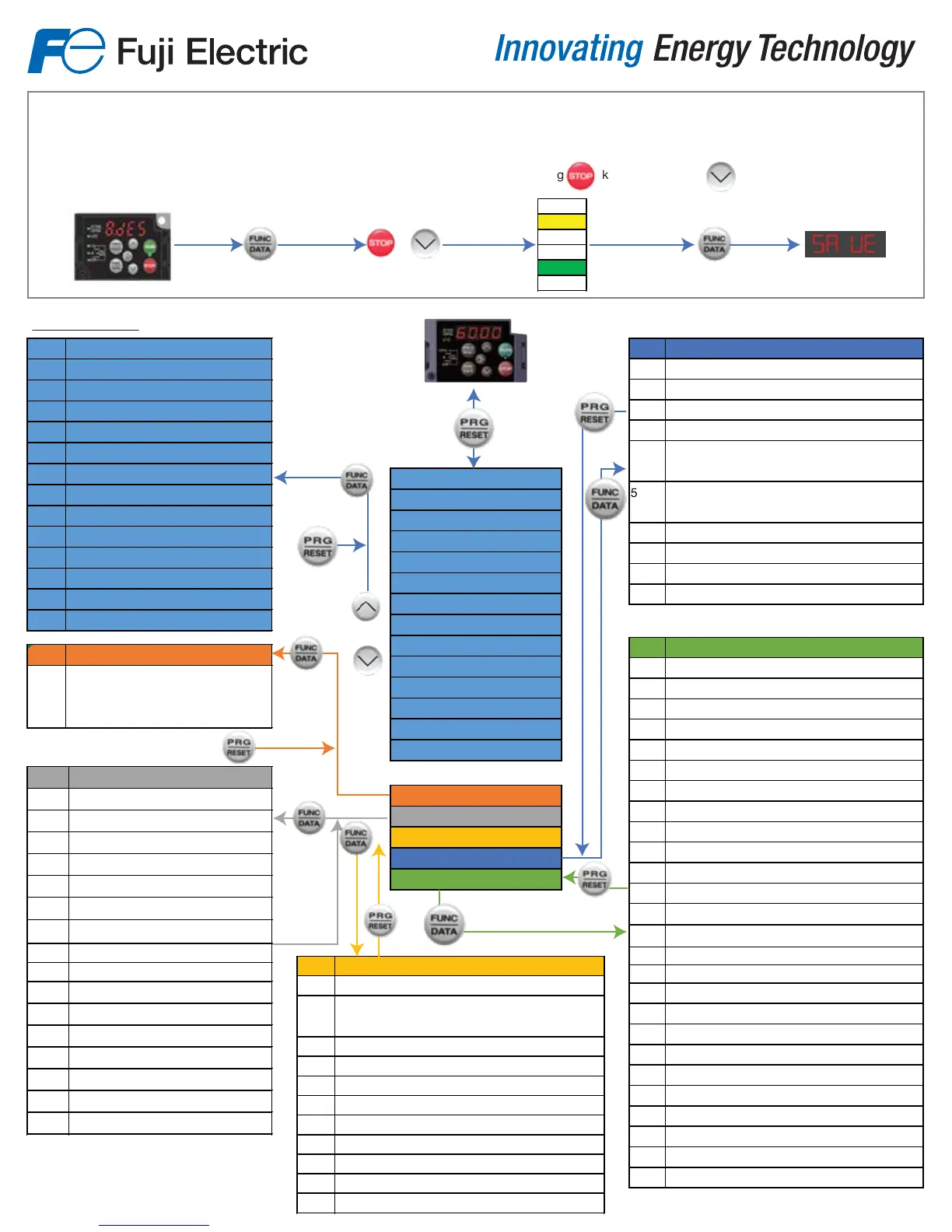
First Power ON.
Upon powering the drive on for the rst time you must set the region in Menu 8.des, for Americas by setting the value to amer
After initial start-up you may change the region by setting the value of H101. See page 4-4 of FRENIC-ACE Instructional Manual INR-SI47-1733f-E For
more details.
Changing the regional from default value
asia to amer requires pressing and holding key while pressing
jpn
asia
chn
eu
amer
kor
savue
+
To access menus 2-6 change function code E52-2

 Loading...


