EasyManua.ls Logo

Fuji Electric FVR2.2AS1S-4

Fuji Electric FVR2.2AS1S-4
32 pages
To Next Page IconTo Next Page
To Previous Page IconTo Previous Page
Loading...
installation
Power
supply
M
3~
Motor
MCCB or
RCD/ELCB
*
Metal panel
Three-
or
single-
phase
Shielded
cable
(Note 1)
* with overcurrent protection
(Note 2)
(Note 3)
EMC-
compliant
filter
(optional)
G
G
N-Micro
L1/R
L2/S
L3/T
U
V
W
G
(L1/L)
(L2/N)
G
(Note 3)
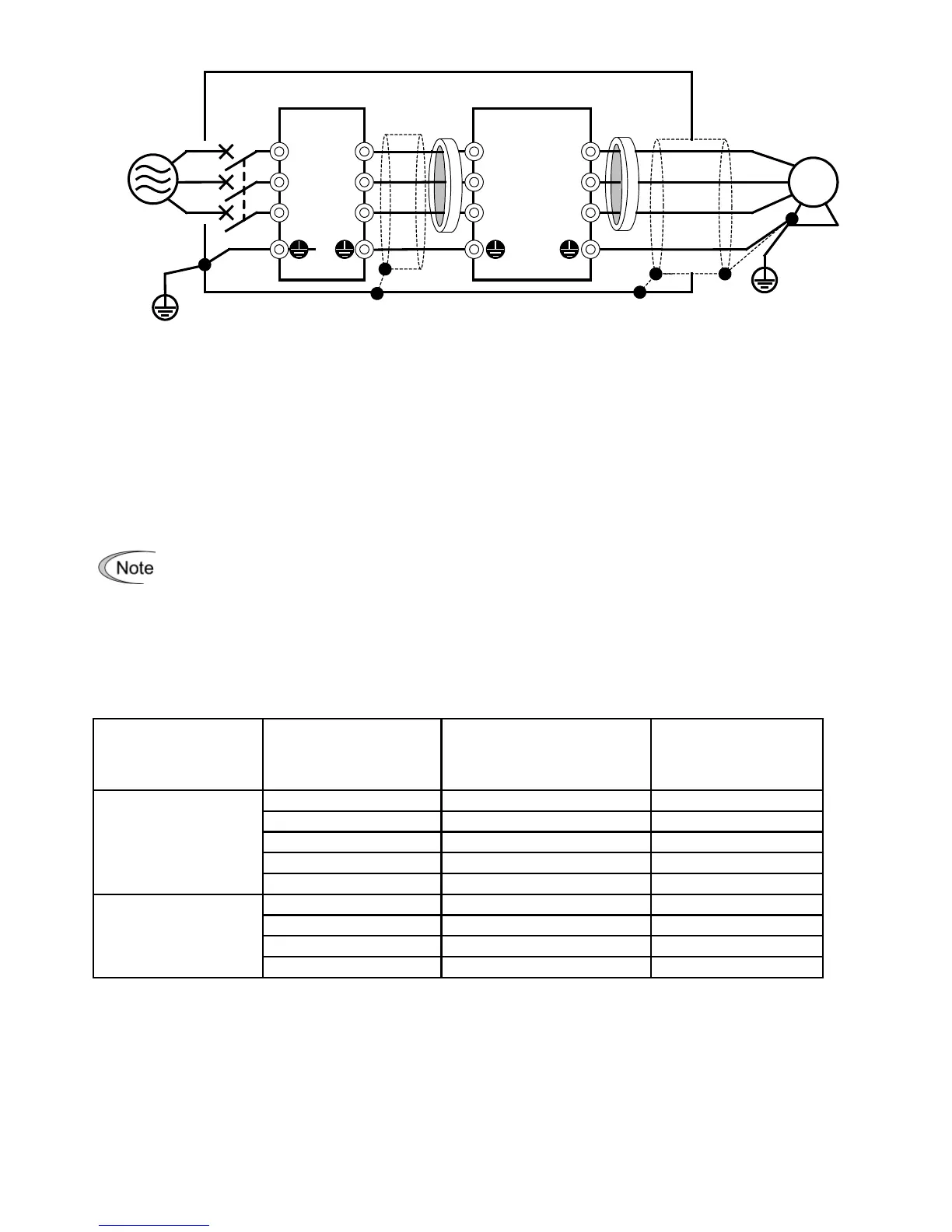
Figure 10.1 Installing the Inverter with EMC-compliant Filter into a Metal Panel
Note 1: Pass the EMC filter input wires (shielded cable and grounding wire in a bundle) through the
ferrite bead core for reducing radio noise two times.
Note 2: Pass the EMC filter output wires (shielded cable and grounding wire in a bundle) through the
ferrite bead core for reducing radio noise two times.
Note 3: Connect the shielding layer of the shielded cable to the motor and panel electrically and
ground the motor and panel.
Radiated noise varies greatly depending upon the installation environment. When no
ferrite
bead core
is used, make sure that the radiated noise does not exceed the
permissible level.
Leakage current
Table 11.2 Leakage Current of EMC-compliant Filter
Input power Inverter type Filter type Leakage current (mA)
Three-phase 400 V
FVR0.4AS1S-4
B84143A0010A166
3.1
FVR0.75AS1S-4
B84143A0010A166
3.1
FVR1.5AS1S-4
B84143A0010A166
3.1
FVR2.2AS1S-4
B84143A0010A166
3.1
FVR3.7AS1S-4
B84143AC020A166
3.1
Single-phase 200 V
FVR0.4AS1S-7
B84142A0010A166
2.59
FVR0.75AS1S-7
B84142A0010A166
2.59
FVR1.5AS1S-7
B84142A0030R166
1.73
FVR2.2AS1S-7
B84142A0030R166
1.73
26

Related product manuals