41S_Rev01
Basic Operation
Splicing procedure
To make a good splice, the optical fiber is observed with the image processing system
equipped in the 36S/37S/38S/41S. However, there are some cases when the image
processing system cannot detect a faulty splice. Visual inspection with the monitor is often
necessary for better splicing yield. The instruction below describes standard operating
procedure.
1. Fibers loaded in the splicer move forward toward each other. The fiber forward
motion stops at a certain position shortly after the cleaning arc is performed.
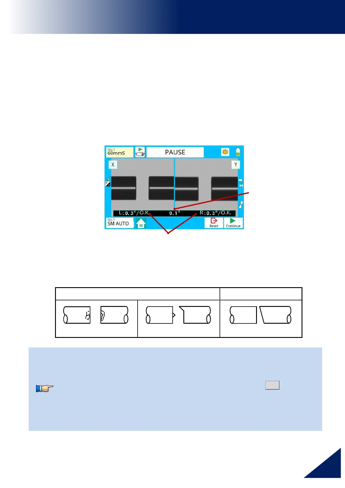
2. Next, the cleave angle and end-face quality are checked. If the measured cleave
angle is greater than its set threshold or fiber chipping is detected, the buzzer will
sound and an error message warns the operator.
3. If no error message is displayed, the end-face conditions are used for visual
inspection as shown below. If observed, remove the fiber from the splicer and
repeat fiber preparation. These visual defects may cause a faulty splice.
The pause after cleave angle check and fiber alignment can be “disabled”.
See section [Splice Settings] for detail.
The cleave angle threshold can be changed. See section [Splice Menu].
The cleave angle error message can be ignored by pressing SET
key to go on
to the next step. To disable the cleave angle error. See section [Splice
Settings] for detail.
Cleave angle, during the splicing operation can be hidden. See section
[Splice Settings] for detail.
Left and Right cleave angle
 Loading...