D
Dana MartinezAug 3, 2025
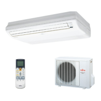
Why is composition control necessary for charging refrigerant R407C in a Fujitsu Air Conditioner?
- CChristine SmithAug 3, 2025
Composition control must be maintained for charging refrigerant because R407C is a zeotropic refrigerant.