If compressor 1, 2, or 3 fails, or if two or more compressors fail at the same time, the remaining compressor(s)
perform temporary operation to prevent interruption of air conditioning system operation by a failure.
When compressor 1, 2, or 3 is judged to be faulty, the system is operated by switching the compressor output
pattern (compressors 0 to 7) as shown in the following table.
Compressor failure is displayed by LEDs on the PCB of the outdoor unit and by output ERROR to the
communication bus line (standard wired remote controller, central remote controller, PC controller).
(a) When compressor 1 (2 HP) fails (compressor 2 is substituted for compressor 1).
(b) When compressor 2 (4 HP) fails (compressor 3 is substituted for compressor 2)
(c) When compressor 3 (6 HP) fails (compressor 1 and 2 are substituted for compressor 3)
x : The compressor is stopped by a protection function or abnormal operation.
(The figures show the compressor capacity (HP) that permits system operation.)
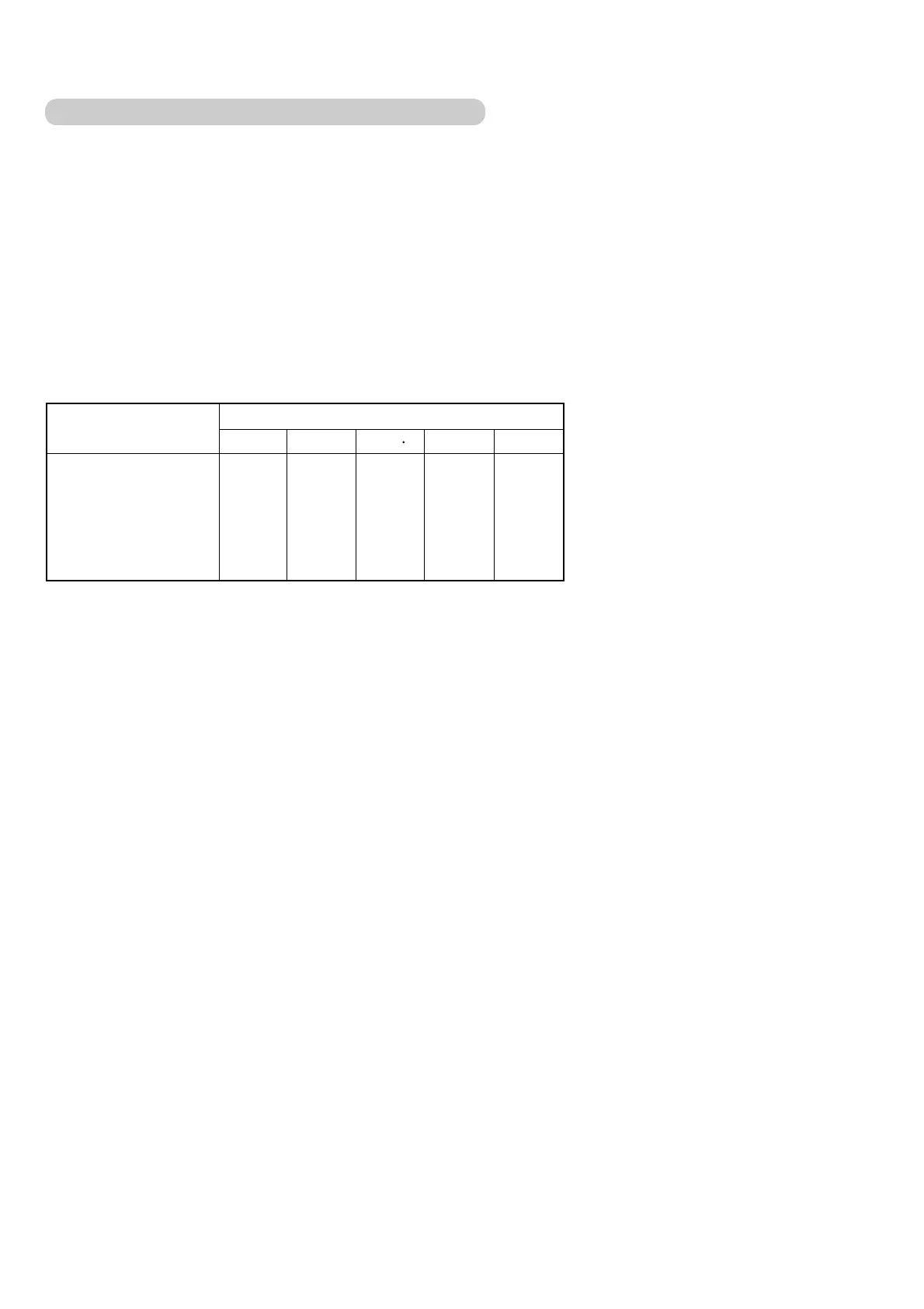
COMPRESSOR RECOVERY OPERATION
ORDINARY OPERATION
RECOVERY OPERATION
(a)X-4-6 (b)2-X-6 (c)2-4 X
Step 0
Step 1
Step 2
Step 3
Step 4
Step 5
Step 6
Step 0
Step 2
Step 2
Step 4
Step 6
Step 6
Step 6
Step 0
Step 1
Step 4
Step 4
Step 5
Step 5
Step 5
Step 0
Step 1
Step 2
Step 3
Step 3
Step 3
Step 3
(d)X-X-6
Step 0
Step 4
Step 4
Step 4
Step 4
Step 4
Step 4
(e)X-4-X
Step 0
Step 2
Step 2
Step 2
Step 2
Step 2
Step 2
5-1-4
COMPRESSOR RECOVERY OPERATION
– 44 –