- (01 - 21) -
FLOOR TYPE
AGU9-15RLF
FLOOR TYPE
AGU9-15RLF
EXTERNAL INPUT & OUTPUT11.
Connector
INPUT
OUTPUT REMARKS
CN14 Control input -
See external input/output
settings for details.
CN20 - Operation status output
CN21 - Error status output
EXTERNAL INPUT11-1.
CONTROL INPUT (Operation/Stop or Forced stop)
The air conditioner can be remotely operated by means of the following on-site work.
"Operation/Stop" mode or "Forced stop" mode can be selected with function setting of indoor unit.
Unit operation is started at the following contents by adding the contact input of a commercial ON/OFF switch to a
connector on the external control PC board and turning it ON.
Unit operation Initial setting after power is ON Starting mode other than initial setting
Operation mode Auto changeover Mode at previous operation
Set temperature 76°F (24°C) Temperature at previous operation
Airow mode AUTO Mode at previous operation
Up-down air direction (swing) Standard air direction (swing OFF) Air direction at previous operation
Left-right air direction (swing) Standard air direction (swing OFF) Air direction at previous operation
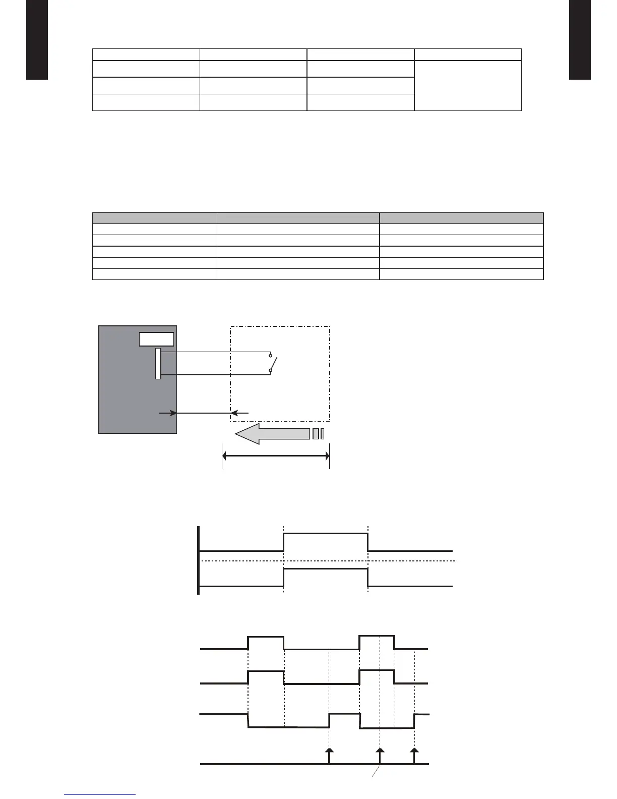
Circuit diagram example
z
Indoor unit
control PC board
Connector
1
3
Signal
Field supply
*33 ft.(10 m)
Connected unit
Ex.) Switch
*: Make the distance from the PC board to the connected unit within 33 ft.(10 m).
Contact capacity: DC 24 V or more, 10 mA or more.