En-10
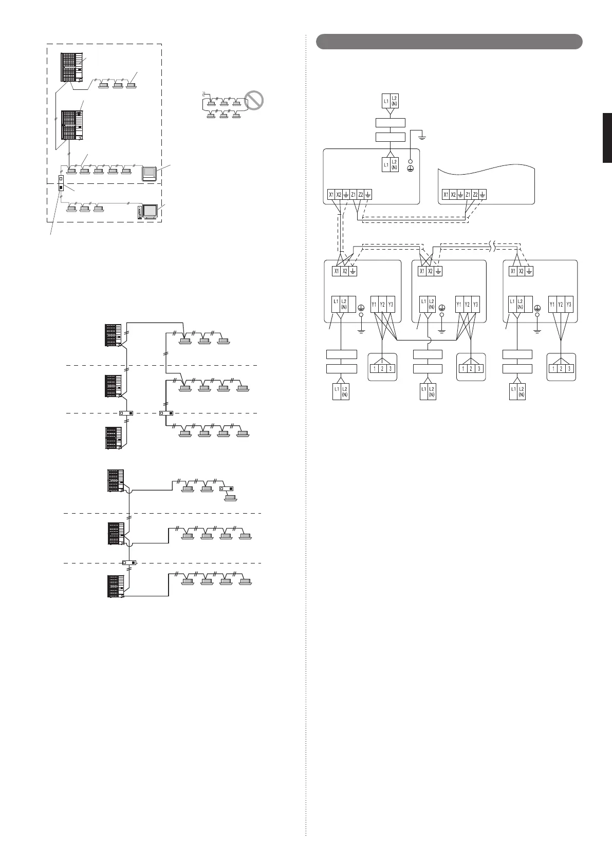
Fig. 2
NOTE:
Do not use loop wiring.
This may lead to parts
damage and erroneous
operation.
Outdoor unit
Indoor unit
Signal Amplifi er
System
Controller
Touc h
Panel
Controller
Transmission line
Terminal resistor
Terminal resistor
NS 1
NS 2
F
H
L
G
K
J
E
6. 4. 3. Enabling/Disabling automatic address setting
You can enable/disable automatic address setting for the indoor unit and the signal ampli-
fi er.
To enable automatic address setting for the indoor unit, connect the indoor unit to outdoor
units under the same refrigerant system.
Example: Disable Automatic Address setting
Refrigerant
system 1
Refrigerant
system 2
Refrigerant
system 3
Transmission line
Transmission line
Transmission line
Example: Enable Automatic Address setting
Refrigerant
system 1
Refrigerant
system 2
Refrigerant
system 3
Transmission line
Transmission line
Transmission line
6. 5. Wiring method
6. 5. 1. Connection diagrams
Breaker 1: Ground Fault Equipment
Breaker (GFEB)
Breaker 2: Maximum Circuit Breaker
(MAX. CKT. BKR)
Power supply
208/230V ~ 60Hz
To other refrigerant circuit
outdoor unit
Outdoor unit
Transmission
Transmission Transmission Transmission
Transmission
Power supply
Remote control Remote control Remote controlPower supply Power supply Power supply
Indoor unit
Power supply
208/230V ~ 60Hz
Remote
controller
*1 *1 *1
Remote
controller
Remote
controller
Power supply
208/230V ~ 60Hz
Power supply
208/230V ~ 60Hz
Indoor unit Indoor unit
Breaker 1
Breaker 1 Breaker 1 Breaker 1
Breaker 2
Breaker 2 Breaker 2 Breaker 2
*1: The number of power supply terminals is different depending on the indoor unit model.
For the wiring, refer to the indoor unit installation manual.
• There are two types of remote controller: the 2-wire type and the 3-wire type. For details,
see the relevant remote controller installation manual. (When connecting the 2-wire type
remote controller, Y3 is not used.)
The wiring example for outdoor and indoor units is shown in fi gure.
6. 5. 2. Wiring procedure
• Remove the service panel. And connect the cable to the terminal in accordance with the
terminal name plate.
• Use a ring terminal to connect the electric cables to the power supply terminal board.
• Keep the earth cable longer than the other cables.
• After connecting the electric cable, secure them with a cable clamp.
• Connect the cable without applying excessive tension.
• Use the specifi ed cable type and connect the cable securely.
Secure with a cable clamp as shown in the fi gure below.
9380545095_IM.indb 109380545095_IM.indb 10 11/17/2015 4:14:26 PM11/17/2015 4:14:26 PM
 Loading...