En-18
8. 3. Additional charging
CAUTION
Do not turn on the power unless all operations are complete.
After evacuating the system, add refrigerant.
Do not charge the system with a refrigerant other than R410A.
Always keep to the limit on the total amount of refrigerant. Exceeding the limit on the
total amount of refrigerant will lead to malfunction during charging of refrigerant.
Do not reuse recovered refrigerant.
Use an electronic scale to measure the charging amount of refrigerant.
Adding more refrigerant than the specifi ed amount will cause a malfunction.
Charge refrigerant using the liquid pipe.
Adding refrigerant through the gas pipe will cause a malfunction.
Add refrigerant by charging the system with the refrigerant in the liquid state. If the refrig-
erant cylinder is equipped with a siphon, it is not necessary to place the cylinder upright.
Check if the steel cylinder has a siphon installed or not before filling. (There is an indica-
tion “with siphon for filling liquid” on the steel cylinder.)
Filling method for cylinder with siphon
Set the cylinder vertical and fill with the
liquid.
(Liquid can be filled without turning bot-
tom up with the siphon inside.)
Liquid
Gas
R410A
Filling method for other cylinders
Turn bottom up and fill with liquid.
(Be careful to avoid turning over the
cylinder.)
Liquid
Gas
R410A
Be sure to use the special tools for R410A for pressure resistance and to avoid mixing of
impure substances.
If the units are further apart than the maximum pipe length, correct operation can not be
guaranteed.
Make sure to back closing valve after refrigerant charging. Otherwise, the compressor
may fail.
Minimize refrigerant release to the air. Excessive release is prohibited under the Freon
Collection and Destruction Law.
8. 3. 1. Procedure for charging the system with refrigerant
(1) Remove the charging port cap from the liquid pipe.
(2) Attach a charging hose to the refrigerant cylinder, and connect it to the charging port.
(3) Add refrigerant by calculating the additional refrigerant volume in accordance with the
calculation formula indicated below.
(4) Remove the charging hose and install the charging port cap.
(5) Remove the blank caps (gas pipe and liquid pipe) and open the valves.
(6) Close the blank caps.
(7) After adding refrigerant, indicate the added charging volume on the unit.
* Tighten the blank caps and charging port caps to the torque values specifi ed in the Table
A. To open and close the valves, use an M4 hexagon wrench.
8. 3. 2. Checking total amount of refrigerant and calculating the
amount of refrigerant charge to be added
• The amount of refrigerant charge to be added is the total value of the basic refrigerant
charge amount and the value calculated from the length of the liquid pipe.
• Round up the value to 2 decimal places.
Model
“B”
Factory charged
amount [lbs (kg)]
Diameter of liquid
pipe [in (mm)]
“a”
Additional amount
for pipe length [lbs/ft
(kg/m)]
AOU36RLAVM 10.58 (4.80)
AOU48RLAVM 11.68 (5.30) Ø 1/4 (6.35) 0.014 (0.021)
AOU60RLAVM 11.68 (5.30) Ø 3/8 (9.52) 0.039 (0.058)
(1) Calculation of additional amount for pipe length
A =
Total length of ø 3/8 in
(ø 9.52 mm) liquid pipe
a × 0.039
(× 0.058)
[lbf/ft (kg/m)]
+
Total length of ø 1/4 in
(ø 6.35 mm) liquid pipe
a × 0.014
(× 0.021)
[lbf/ft (kg/m)]
ft (m) ft (m)
lbs (kg) lbs (kg)
=
Total
lbs (kg)
(Round up A to 2 decimal place)
(2) Calculation of total refrigerant amount
C = A+B =
lbs (kg)
(B : Factory charged amount)
NOTE:
Check the total refrigerant amount under the following conditions
Condition Computational formula
Total amount of refrigerant C ≤
34.61
lbs (15.7 kg)
<Calculation>
Outdoor unit: AOU60RLAVM
(1) Calculation of additional amount for outdoor unit
If liquid pipe piping length is the following
Ø 3/8 in: 164 ft, Ø 1/4 in: 114 ft
(
Ø
9.52 mm: 50 m ,
Ø
6.35 mm: 35 m)
Additional charge volume:
A = 164 ft × 0.039 lbf/ft +
114 ft
× 0.014 lbf/ft
(A = 50 m × 0.058 kg/m +35 m × 0.021 kg/m)
= 8.01 lbs
(= 3.635 kg ≈ 3.64 kg)
(2) Check the total amount of refrigerant
C = A + B = 8.01 lbs + 11.68 lbs = 19.69 lbs ≤
34.61
lbs
(C = A + B = 3.64 kg + 5.30 kg = 8.94 kg ≤
15.7
kg)
→No problem if the above condition is satisfi ed.
8. 4. Installing insulation
• Install insulation material after conducting the “8.1 Sealing test”.
• To prevent condensation and water droplets, install insulation material on the refrigerant
pipe.
• Refer to the table to determine the thickness of the insulation material.
• If the outdoor unit is installed at a level that is higher than the indoor unit, the water that
has condensed in the 3-way valve of the outdoor unit could travel to the indoor unit.
Therefore, use putty in the space between the pipe and the insulation to prevent the
entry of water.
Table. Selection of insulation
[Use an insulation material with equal heat transmission rate or below
0.023 BTU/ft·h·°F(0.040 W/m·k)]
Insulation material
Minimum thickness [in (mm)]
Relative humidity ≤ 70% ≤ 75% ≤ 80% ≤ 85%
Pipe diameter
[in (mm)]
1/4 (6.35) 5/16 (8) 3/8 (10) 1/2 (13) 11/16 (17)
3/8 (9.52) 3/8 (9) 7/16 (11) 9/16 (14) 11/16 (18)
1/2 (12.70) 3/8 (10) 1/2 (12) 9/16 (15) 3/4 (19)
5/8 (15.88) 3/8 (10) 1/2 (12) 5/8 (16) 13/16 (20)
3/4 (19.05) 3/8 (10) 1/2 (13) 5/8 (16) 13/16 (21)
* When an ambient temperature and relative humidity exceed 90 °F (32 °C), please
strengthen heat insulation of refrigerant pipe.
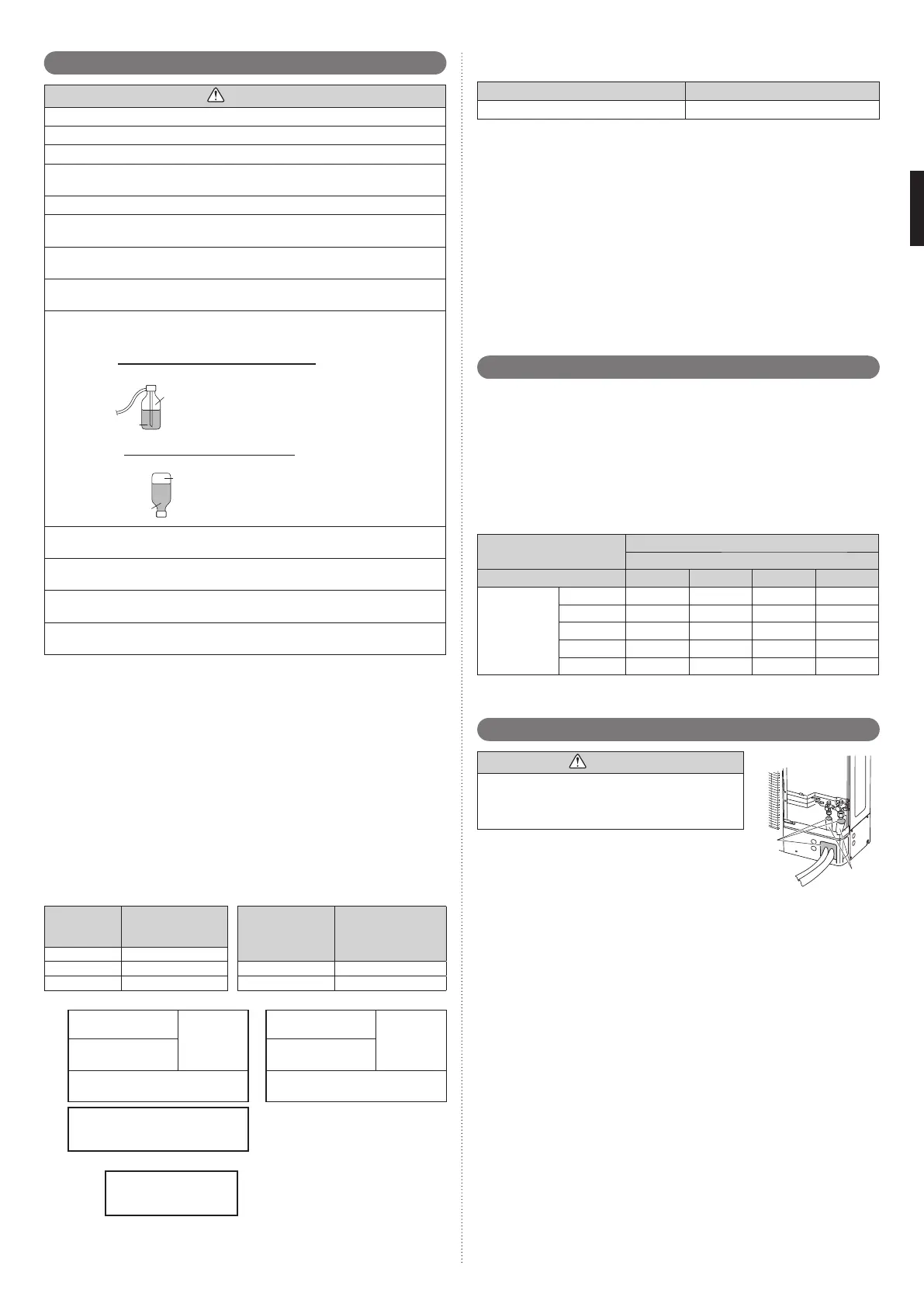
8. 5. Filling with putty
WARNING
Putty
Insulation
Fig. A
Fill the piping holes and wiring holes with putty (supplied
locally) to avoid any gap (Fig A). If small animals such
as insects enter the external unit, a short circuit may be
caused near electrical components in the service panel.
If the outdoor unit is installed at a level that is higher than
the indoor unit, the water that has condensed in the 3-way
valve of the outdoor unit could travel to the indoor unit.
Therefore, use putty in the space between the pipe and the
insulation to prevent the entry of water to the indoor units.
9380545095_IM.indb 189380545095_IM.indb 18 11/17/2015 4:14:29 PM11/17/2015 4:14:29 PM
 Loading...