En-9
L
Check if [L] is fl ared uniformly
and is not cracked or scratched.
Pipe
A
B
Die
Pipe outside
diameter [in. (mm)]
Dimension A [in. (mm)]
Dimension B
0
- 0.4
[in. (mm)]
Flare tool for R410A,
clutch type
1/4 (6.35)
0 to 0.020 (0 to 0.5)
3/8 (9.1)
3/8 (9.52) 1/2 (13.2)
1/2 (12.70) 5/8 (16.6)
5/8 (15.88) 3/4 (19.7)
3/4 (19.05) 15/16 (24.0)
• When using conventional fl are tools to fl are R410A pipes, the dimension A should
be approximately 0.020 in. (0.5 mm) more than indicated in the table (for fl aring
with R410A fl are tools) to achieve the specifi ed fl aring. Use a thickness gauge to
measure the dimension A.
Pipe outside
diameter
[in. (mm)]
Width across fl ats
of Flare nut
[in. (mm)]
1/4 (6.35) 11/16 (17)
3/8 (9.52) 7/8 (22)
1/2 (12.70) 1 (26)
5/8( 15.88) 1-1/8 (29)
3/4 (19.05) 1-7/16 (36)
Width across fl ats
5. 1. 2. Bending pipes
CAUTION
To prevent breaking of the pipe, avoid sharp bends. Bend the pipe with a radius of
curvature of 4 in. (100 mm) or more.
If the pipe is bent repeatedly at the same place, it will break.
• If pipes are shaped by hand, be careful not to collapse them.
• Do not bend the pipes at an angle of more than 90°.
• When pipes are repeatedly bent or stretched, the material will harden, making it
diffi cult to bend or stretch them any more.
• Do not bend or stretch the pipes more than 3 times.
5. 1. 3. Connecting pipes
CAUTION
Be sure to install the pipe against the port on the indoor unit and the outdoor unit
correctly. If the centering is improper, the flare nut cannot be tightened smoothly.
If the fl are nut is forced to turn, the threads will be damaged.
Do not remove the fl are nut from the outdoor unit pipe until immediately before con-
necting the connection pipe.
After installing the piping, make sure that the connection pipes do not touch the com-
pressor or outer panel. If the pipes touch the compressor or outer panel, they will
vibrate and produce noise.
If there are a large number of fl are connections due to the number of indoor units con-
nected, please confi rm that the valves that are not connected are closed.
Not doing so may cause a refrigerant leak.
When connecting the indoor unit, it should be connected in the order of port A, B, C,
and so on. Please be sure to close remaining unconnected ports so that they do not
leak refrigerant.
(1) Detach the caps and plugs from the pipes.
(2) Center the pipe against the port on the outdoor unit, and then turn the fl are nut
by hand.
To prevent gas leakage, coat the fl are
surface with alkylbenzene oil (HAB).
Do not use mineral oil.
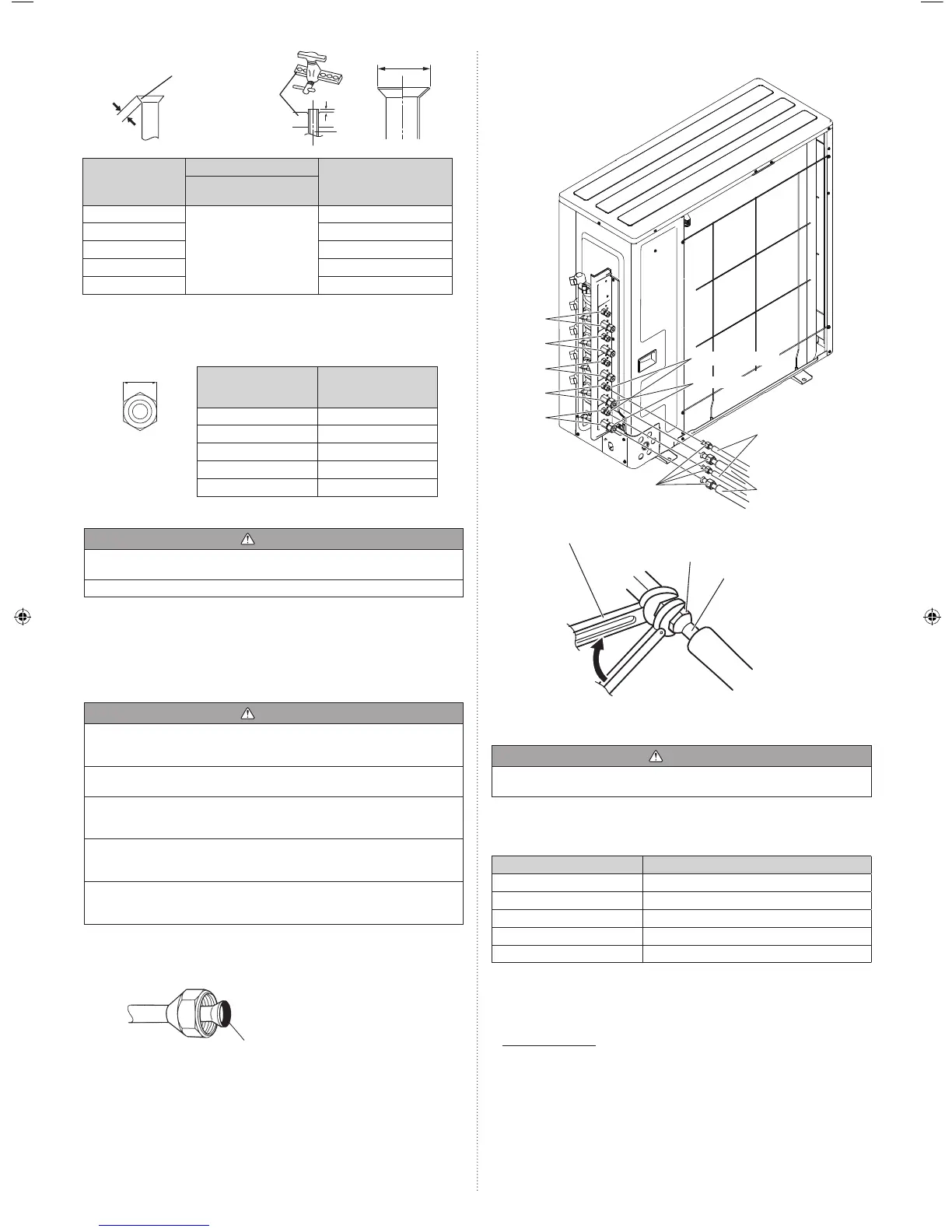
(3) Attach the connection pipe.
Example: 45 type
Connection pipe
(Liquid)
Connection pipe
(Gas)
Flare nut
Valve (Liquid)
Valve (Gas)
Port A
Port B
Port C
Port D
Port E
Holding
wrench
Insulation of the
connection pipe
Torque wrench
Body side
Flare nut
With this model, the Holding wrench
can only be inserted horizontally.
To prevent condensation
from dropping, insulate the
gap between the fl are nut
and the insulation of the
connection pipe.
(4) When the fl are nut is tightened properly by your hand, use a torque wrench to
fi nally tighten it.
CAUTION
Hold the torque wrench at its grip, keeping it in a right angle with the pipe, in order to
tighten the fl are nut correctly.
• Outer panel may be distorted if fastened only with a wrench. Be sure to fi x the
elementary part with a holding wrench and fasten with a torque wrench (refer to below
diagram). Do not apply force to the blank cap of the valve or hang a wrench, etc., on the
cap. If blank cap is broken, it may cause leakage of refrig
erant.
Flare nut [in. (mm)] Tightening torque [lbf·ft. (N·m)]
1/4 (6.35) dia. 11.8 to 13.3 (16 to 18)
3/8 (9.52) dia. 23.6 to 31.0 (32 to 42)
1/2 (12.70) dia. 36.1 to 45.0 (49 to 61)
5/8 (15.88) dia. 46.5 to 55.3 (63 to 75)
3/4 (19.05) dia. 66.4 to 81.1 (90 to 110)
5. 1. 4. Handling precautions for the valves
• Mounted part of Blank cap is sealed for protection.
• Fasten blank cap tightly after opening valves.
Operating the valves
• Use a hexagon wrench [size: 3/16 in. (4 mm)].
• Opening (1) Insert the hexagon wrench into the valve shaft, and turn it
counterclockwise.
(2) Stop turning when the valve shaft can no longer be turned.
(Open position)
• Closing (1) Insert the hexagon wrench into the valve shaft, and turn it
clockwise.
(2) Stop turning when the valve shaft can no longer be turned.
(Closed position)
9380545101-02_IM.indb 99380545101-02_IM.indb 9 2/26/2016 10:16:04 AM2/26/2016 10:16:04 AM
 Loading...