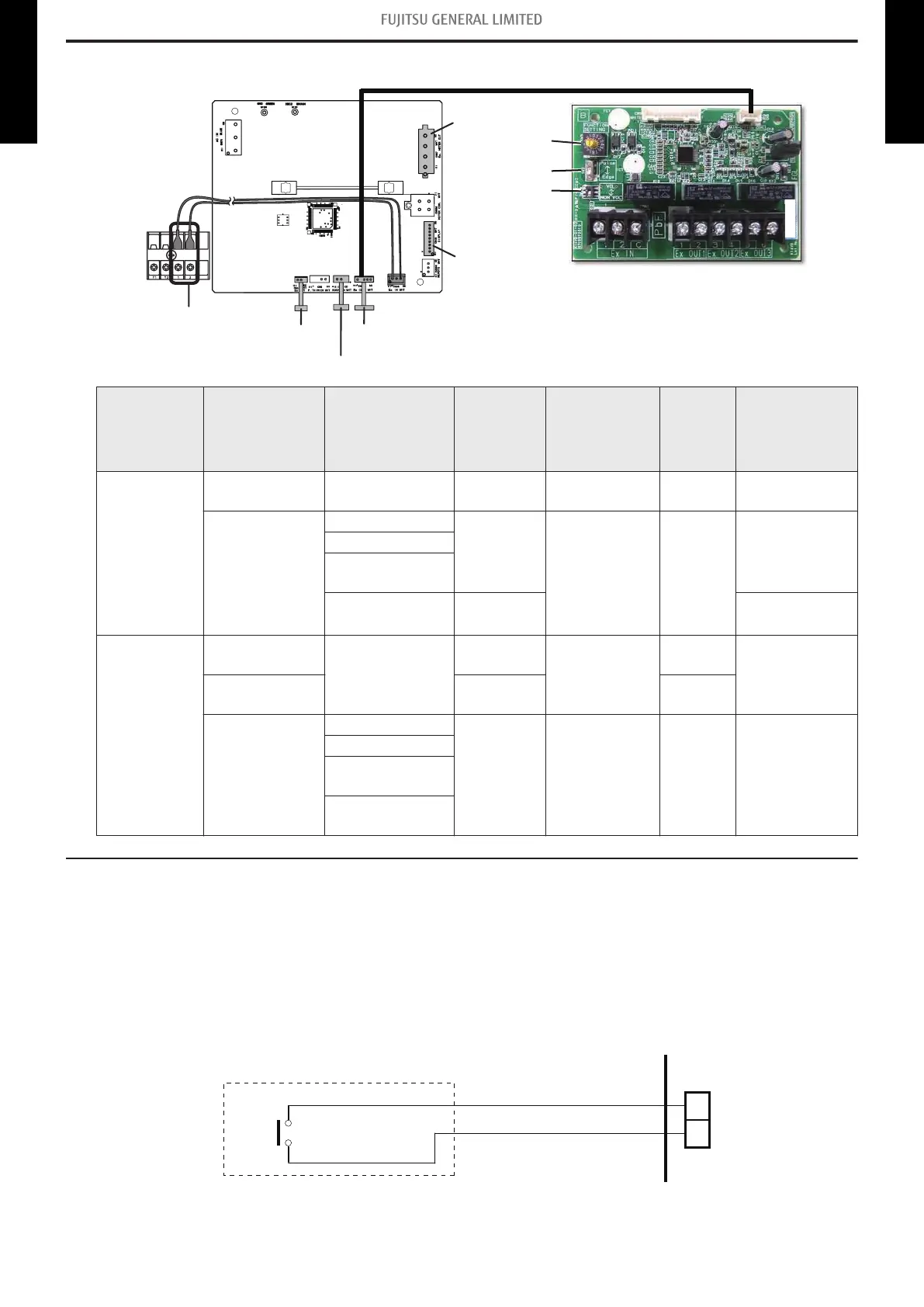
6. External input and output
Terminal
(External in)
IR receiver
External in/out PCB (Connect with Wire kit)External out
External Heater
Remote sensor
Rotary switch
SW2
SW1
Fig. External input and output PCB
CN65CN47 CN5
CN48
CN67
SW101
PCB External input External output Connector Input select
Input
signal
External
connect kit
(Optional
parts)
Indoor unit
Operation/Stop
Forced stop
— Terminal Dry contact Edge —
—
Operation status
CN47
— —
UTY-XWZXZG
Error status
Indoor unit fan
operation status
External heater
output
CN47
CN67
External input
and output
(UTY-XCSX)
Operation/Stop
—
Input 1/
Input 2
Dry contact/
Apply voltage
Edge/
Pulse
—
Forced
thermostat off
Input 1 Edge
—
Operation status
Output 1
Output 2
Output 3
— — —
Error status
Indoor unit fan
operation status
External heater
output
6-1. External input
• “Operation/Stop” mode or "Forced stop" mode can be selected with function setting of indoor unit.
• A twisted pair cable (22AWG) should be used. Maximum length of cable is 492 ft (150 m).
• The wire connection should be separate from the power cable line.
¢
Indoor unit
Indoor unit functions such as Operation/Stop can be done by using indoor unit terminals.
*1: The switch can be used on the following condition: DC 12 V to 24 V, 1 mA to 15 mA.
- 20 -
6-1. External input 6. External input and output
DUCT TYPE
AMUG24-48LMAS
DUCT TYPE
AMUG24-48LMAS
 Loading...

