Do you have a question about the Fujitsu AOYG09LLC and is the answer not in the manual?
Technical electrical parameters for indoor and outdoor units.
Sound pressure levels for indoor and outdoor units.
Details on compressor type, refrigerant, and charge.
Fan motor speed specifications for different operating modes.
Physical size specifications for indoor and outdoor units.
Net and shipping weight for indoor and outdoor units.
Detailed dimensions of the indoor unit with diagrams.
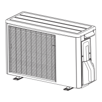
Detailed dimensions of the outdoor unit with diagrams.
Wiring diagram for the indoor unit main control board.
Wiring diagram for the outdoor unit main control board.
Circuit details for the indoor unit control system.
Detailed circuit diagram for the indoor unit main PCB.
Circuit diagram for the indoor unit indicator PCB.
Remote control unit for the air conditioner.
Mounting bracket for the indoor unit.
Front panel assembly for the indoor unit.
Filter component for the indoor unit.
Cover for internal wiring.
Shielding for internal wiring.
Adjustable louver for airflow direction.
General panel cover for the indoor unit.
Protective cover for the control box.
Housing for the main electronic components.
Shielding assembly for the control box.
Main printed circuit board for model 09.
Main printed circuit board for model 12.
Connection terminals for wiring.
Terminal for electrical earth connection.
Assembly for the unit display.
Holder for the room thermistor sensor.
Assembly containing the thermistor sensor.
Motor that drives the fan.
Fan assembly for airflow.
Bearing assembly for the fan.
Main casing structure for the fan.
Main housing of the indoor unit.
Cover for the motor component.
Front casing cover.
Rear casing cover.
Right and left louvers for airflow.
Motor controlling louvers or flaps.
Protective guard for the fan.
Cap for the drain outlet.
Assembly for the drain hose.
Complete evaporator assembly for model 09.
Complete evaporator assembly for model 12.
Terminal for electrical earth connection.
Right side holder for the evaporator.
Left side holder for the evaporator.
Mounting bracket at the rear.
Guide for air filter placement.
Optional protective net for the outdoor unit.
Optional protective net for the outdoor unit.
Holder for thermistor sensors.
Top panel assembly of the outdoor unit.
Front panel assembly of the outdoor unit.
Left side cabinet assembly.
Right side cabinet assembly.
Cover assembly for switches.
Motor for the outdoor unit fan.
Fan blade assembly.
Base structure of the outdoor unit.
Assembly for the drain system.
Brand emblem or logo.
Reactor assembly for model 09.
Reactor assembly for model 12.
Holder for printed circuit boards.
Main PCB with terminals for model 09.
Main PCB with terminals for model 12.
Assembly containing thermistor sensors.
Thermistor sensor component.
Heat sink for model 09.
Heat sink for model 12.
Complete condenser assembly for model 09.
Compressor assembly for the outdoor unit.
Solenoid valve component.
Four-way valve assembly.
Muffler for refrigerant system.
Three-way valve assembly.
Capillary tube assembly.
Two-way valve assembly.
Complete condenser assembly for model 12.
Compressor assembly for the outdoor unit.
Solenoid valve component.
Four-way valve assembly.
Muffler for refrigerant system.
Three-way valve assembly.
Capillary tube assembly.
Two-way valve assembly.
Bracket for mounting the indoor unit.
Handheld remote control unit.
Penlight batteries for the remote control.
Adhesive cloth tape.
Large tapping screws for installation.
Assembly for the condensate drain pipe.
| Brand | Fujitsu |
|---|---|
| Model | AOYG09LLC |
| Category | Air Conditioner |
| Language | English |