Do you have a question about the Fujitsu AOYG09KHCAN and is the answer not in the manual?
Provides detailed specifications for indoor units, including model names, power, capacity, input, and performance data.
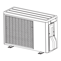
Details specifications for outdoor units, covering models, power, fan, sound levels, heat exchangers, and components.
Safety precautions and guidelines for service personnel before starting any maintenance or repair work.
Lists exterior parts and accessories for indoor units with item numbers, part numbers, and names.
Details the components of the control box for indoor units, including PCBs, terminals, and sensors.
Lists components of the evaporator and fan assembly for indoor units, including motors and casings.
Details the casing assembly for indoor units, including covers and the main casing.
Illustrates the motor case assembly for indoor units, showing gears, motors, and covers.
Lists components of the casing assembly for indoor units, including casing covers and pipe brackets.
Lists exterior parts for outdoor units, including thermistors, protective nets, and panels.
Details the chassis components of outdoor units, including panels, fans, motors, and base assembly.
Lists components of the outdoor unit control system, including main PCBs, heat sinks, and insulators.
Illustrates the refrigeration cycle components of outdoor units, including condensers, valves, and compressors.
Lists error codes for indoor and outdoor units and their corresponding indicator patterns.
Provides a table correlating error contents with indoor unit display indicators and remote controller codes.
Troubleshooting steps for serial communication error (reverse transfer) in outdoor units, including connection and voltage checks.
Troubleshooting steps for serial communication error (forward transfer) in indoor units, covering connection and signal checks.
Troubleshooting steps for wired remote controller communication errors, focusing on terminal connections and voltage.
Troubleshooting for indoor unit main PCB errors, involving power reset, component checks, and PCB replacement.
Troubleshooting steps for MANUAL AUTO button errors, including button checks and PCB replacement.
Troubleshooting for room temperature sensor errors in indoor units, involving connector checks and resistance values.
Troubleshooting for indoor heat exchanger sensor errors, focusing on connections and thermistor resistance.
Troubleshooting steps for indoor unit fan motor errors, including fan rotation, ambient temperature, and motor checks.
Troubleshooting for outdoor unit main PCB errors, involving power reset, PCB replacement, and external causes.
Troubleshooting for PFC circuit errors in outdoor units, addressing voltage drops, noise, and PCB issues.
| Cooling Capacity | 2.5 kW |
|---|---|
| Heating Capacity | 3.2 kW |
| Power Supply | 220-240V, 50Hz |
| Refrigerant | R32 |
| Indoor Unit Dimensions (W x H x D) | 790 x 293 x 206 mm |
| Outdoor Unit Dimensions (W x H x D) | 663 x 541 x 290 mm |
| Noise Level (Indoor) | 21 dB(A) |