En-7
6. INSTALLATION WORK
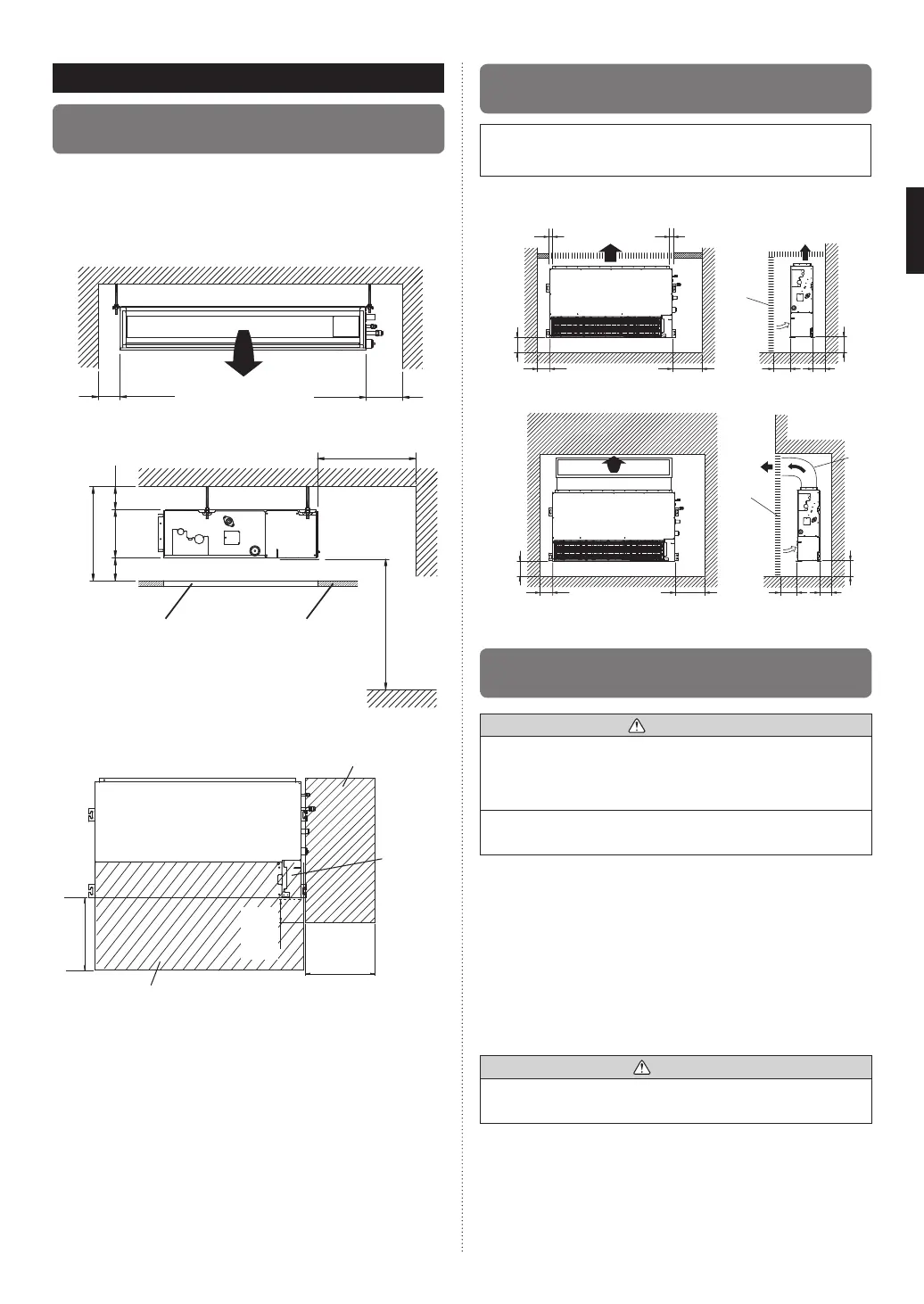
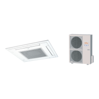
6.1A. Installation dimensions (Ceiling
concealed type)
Provide a service access for inspection purposes.
Do not place any wiring or illumination in the service space,
as they will impede service.
Installation Dimensions
Left
side
Strong and durable ceiling
Indoor unit
Right
side
4 (100) or
more
12 (300) or
more
unit: in. (mm)
Service access Ceiling
9ft (2500) or more
(When no ceiling)
Floor
10 (240) or more
1 (20) or more
1 (20) or more
12 (300) or more
Adjust the wind direction in the room depending on the
shape of blow out opening.
Service access
Unit
Control
box
12 (300) or
more
4 (100) or
more
12 (300) or
more
Service space
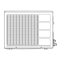
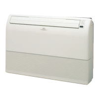
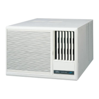
6.1B.
Installation dimensions (Wall mounted
type/Floor standing concealed type)
The wall mounted type/floor standing concealed type re-
quires a temperature correction setting. Perform this in “10.3.
Function setting”.
Strong and
durable floor
1 (10) or
less
Left side
Left side
6 (150)
or more
6 (150)
or more
6 (150)
or
more
6 (150)
or
more
4 (100) or
more
4 (100) or
more
1 (20) or
more
1 (20) or
more
1 (20) or
more
1 (20) or
more
12 (300) or
more
12 (300) or
more
Inlet air
Inlet air
Strong and
durable floor
Strong and
durable floor
1 (10) or
less
Right side
(PIPE side)
Right side
(PIPE side)
Grill
Duct
Grill
Strong and
durable floor
unit: in. (mm)
6.2A. Install the unit (Ceiling concealed
type)
WARNING
Install the air conditioner in a location which can withstand a
load do at least 5 times the weight of the main unit and which
will not amplify sound or vibration. If the installation location is
not strong enough, the indoor unit may fall and cause injuries.
If the job is done with the panel frame only, there is a risk that
the unit will come loose. Please take care.
6.2A.1. UNIT INSTALLATION EXAMPLE (CEILING
CONCEALED TYPE)
Connect the locally purchased duct.
(1) Inlet side
• Connect the duct to the locally purchased inlet fl ange.
• Connect the fl ange to the body with the locally purchased
tapping screws.
• Wind the inlet flange connecting to the duct with the
aluminum tape etc. to avoid the air discharge.
CAUTION
When the duct is connected to inlet side, remove contained
fi lter and surely attach locally purchased fi lter at inlet opening.
(2) Outlet side
• Connect the duct with adjusting inside of outlet fl ange.
• Wind the outlet flange connecting to the duct with the
aluminum tape etc. to avoid the air discharge.
• Insulate the duct to avoid the dew condensation.
9374342419_02_IM.indb 79374342419_02_IM.indb 7 2015/6/25 10:27:042015/6/25 10:27:04