Indoor unit is an appliance not accessible to the general public.
For authorized service personnel only.
This mark indicates procedures which, if improperly performed, are most likely to result in
the death of or serious injury to the user or service personnel.
This mark indicates procedures which, if improperly performed, might lead to the death or
serious injury of the user.
This mark indicates procedures which, if improperly performed, might possibly result in
personal harm to the user, or damage to property.
DANGER
Never touch electrical components immediately after the power supply has been turned off. Electrical shock
may occur. After turning off the power, always wait 5 minutes or more before touching electrical components.
This air conditioner uses new refrigerant HFC (R410A).
The basic installation work procedures are the same as conventional refrigerant models.
However, pay careful attention to the following points:
Since the working pressure is 1.6 times higher than that of conventional refrigerant models, some of the
piping and installation and service tools are special. (See the table below.)
Especially, when replacing a conventional refrigerant model with a new refrigerant R410A model, always
replace the conventional piping and flare nuts with the R410A piping and flare nuts.
Models that use refrigerant R410A have a different charging port thread diameter to prevent erroneous
charging with conventional refrigerant and for safety. Therefore, check beforehand. [The charging port thread
diameter for R410A is 1/2 UNF 20 threads per inch.]
Be more careful that foreign matter (oil, water, etc.) does not enter the piping than with refrigerant models.
Also, when storing the piping, securely seal the openings by pinching, taping, etc.
When charging the refrigerant, take into account the slight change in the composition of the gas and liquid
phases, and always charge from the liquid phase side whose composition is stable.
Special tools for R410A
Copper pipes
It is necessary to use seamless copper pipes and it is desirable that the amount
of residual oil is less than 40 mg/10m. Do not use copper pipes having a col-
lapsed, deformed or discolored portion (especially on the interior surface). Oth-
erwise, the expansion valve or capillary tube may become blocked with con-
taminants.
As an air conditioner using R410A incurs pressure higher than when using
conventional refrigerant, it is necessary to choose adequate materials.
Thicknesses of copper pipes used with R410A are as shown in the table. Never
use copper pipes thinner than that in the table even when it is available on the
market.
DANGER
WARNING
CAUTION
Contents of change
Pressure is high and cannot be measured with a conventional gauge. To prevent erroneous mixing of
other refrigerants, the diameter of each port has been changed.
It is recommended the gauge with seals –0.1 to 5.3 MPa (–76 cmHg to 53 kgf/cm
2
) for high pressure.
–0.1 to 3.8 MPa (–76 cmHg to 38 kgf/cm
2
) for low pressure.
To increase pressure resistance, the hose material and base size were changed.
A conventional vacuum pump can be used by installing a vacuum pump adapter.
Special gas leakage detector for HFC refrigerant R410A.
Tool name
Gauge manifold
Charge hose
Vacuum pump
Gas leakage detector
Thicknesses of Annealed Copper Pipes (R410A)
Thickness
0.80 mm
0.80 mm
0.80 mm
Pipe outside diameter
6.35 mm (1/4 in.)
9.52 mm (3/8 in.)
12.70 mm (1/2 in.)
SPLIT TYPE AIR CONDITIONER
INSTALLATION
INSTRUCTION SHEET
(PART NO. 9374815012-02)
CAUTION
R410A
REFRIGERANT
This Air Conditioner contains and operates
with refrigerant R410A and Polyol Ester oil.
THIS PRODUCT MUST ONLY BE INSTALLED OR SERVICED
BY QUALIFIED PERSONNEL.
Refer to Commonwealth, State, Territory and local legislation,
regulations, codes, installation & operation manuals, before
the installation, maintenance and /or service of this product.
Connection cord (mm
2
)
MAX.
2.5
MIN.
1.5
CONNECTING PIPE REQUIREMENT
CAUTION
Refer to the installation instruction sheet of the outdoor unit for description of the length of connecting pipe or
for difference of its elevation.
CAUTION
Install heat insulation around both the gas and liquid pipes. Failure to do so may cause water leaks.
Use heat insulation with heat resistance above 120 °C. (Reverse cycle model only)
In addition, if the humidity level at the installation location of the refrigerant piping is expected to exceed 70%,
install heat insulation around the refrigerant piping. If the expected humidity level is 70-80%, use heat insulation
that is 15 mm or thicker and if the expected humidity exceeds 80%, use heat insulation that is 20 mm or thicker.
If heat insulation is used that is not as thick as specified, condensation may form on the surface of the insulation.
In addition, use heat insulation with heat conductivity of 0.045 W/(m·K) or less (at 20 °C).
ELECTRICAL REQUIREMENT
• Always use H07RN-F or equivalent to the connection cord.
• Install all electrical works in accordance to the standard.
• Install the disconnect device with a contact gap of at least 3 mm in all poles nearby the units. (Both indoor unit and outdoor unit)
• Electric wire size :
••
••
• Use pipe with water-resistant heat insulation.
••
••
• Use pipe that can withstand a pressure of 4150 kpa.
MODEL
Diameter
Small
Large
9000 and 12000 14000 - 22000 BTU/h
BTU/h models models
6.35 mm (1/4 in.) 6.35 mm (1/4 in.)
9.52 mm (3/8 in.) 12.70 mm (1/2 in.)
1
INDOOR UNIT
INSTALLATION
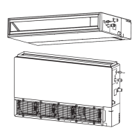
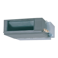
A. CEILING CONCEALED TYPE
1. INSTALL THE FILTERS
• Install the filters to the unit.
Filter
[12000 - 22000 BTU/h
models]
[9000 BTU/h model]
Unit
Filter
This unit may also be installed with the air inlet facing down.
See also
1
- B - 1 for such cases.
2. DRILLING HOLES FOR BOLTS AND IN-
STALLING THE BOLTS
• Using the installation template, drill holes for bolts (4 holes).
3. INSTALLING THE HANGERS
• Fasten the hanging bolts to the ceiling and install special nuts A
and B.
• Install the hangers to the unit (4 places).
• Hang the unit.
Pass the hanging bolts through the hangers (4 places).
CAUTION
Fasten the unit securely with special nuts A and B.
4. LEVELING
Base horizontal direction leveling on top of the unit.
5. SERVICE HOLE DIMENSIONS
Open a service hole with the dimensions shown.
Service hole
Control box
30 cm (1 )
or more
10 cm (4 )
or more
Unit
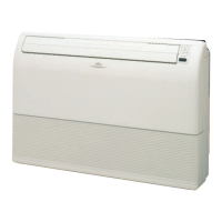
B.
FLOOR STANDING CONCEALED TYPE
1. INSTALL THE FILTERS
• Remove the 4 tapping screws, and then remove cover.
• Install the cover with the 4 tapping screws as shown in the illus-
tration below.
Tapping scre
Cover
[12000 - 22000 BTU/h
models]
[9000 BTU/h model]
• Install the filters to the unit referring to
1
- A -1.
[12000 - 22000 BTU/h
models]
[9000 BTU/h model]
3. DRILLING HOLES FOR BOLTS AND IN-
STALLING THE BOLTS
• Drilling position for bolts.
CAUTION
Secure with an M10 anchor bolts. If securing the unit
to the floor is difficult, first build a stand or platform.
[12000 - 22000
BTU/h models]
[9000 BTU/h model]
4. INSTALL THE UNIT
• Fix the unit.
Install the unit and fasten with special nut B.
5. LEVELING
Base horizontal and vertical direction leveling on top of the unit.
CAUTION
In order to prevent water from leaking around the out-
let port, make sure to insulate it (on both the CEIL-
ING CONCEALED type and the FLOOR STANDING
CONCEALED type).
2. INSTALLING THE HANGERS
• Install the hangers to the unit (4 places).
CONNECTING THE
PIPE
CAUTION
Do not use mineral oil on flared part. Prevent min-
eral oil from getting into the system as this would
reduce the lifetime of the units.
While welding the pipes, be sure to blow dry ni-
trogen gas through them.
1. FLARING
(1) Cut the connection pipe to the necessary length with a pipe
cutter.
(2) Hold the pipe downward so that cuttings will not enter the pipe
and remove the burrs.
(3) Insert the flare nut (always use the flare nut attached to the
indoor and outdoor units respectively) onto the pipe and per-
form the flare processing with a flare tool.
Use the special R410A flare tool, or the conventional (for R22)
flare tool.
Check if [L] is flared uniformly
and is not cracked or scratched.
L
Die
A
Pipe
B
When using conventional flare tools to flare R410A pipes, the di-
mension A should be approximately 0.5 mm more than indicated in
the table (for flaring with R410A flare tools) to achieve the specified
flaring. Use a thickness gauge to measure the dimension A.
2
Pipe outside diameter
Dimension A (mm)
Flare tool for R410A, clutch type
6.35 mm (1/4 in.)
9.52 mm (3/8 in.)
12.70 mm (1/2 in.)
0 to 0.5
Pipe outside diameter Dimension B (mm)
6.35 mm (1/4 in.)
9.52 mm (3/8 in.)
12.70 mm (1/2 in.)
0
-0.4
9.1
13.2
16.6
Pipe outside
diameter
6.35 mm (1/4 in.)
9.52 mm (3/8 in.)
12.70 mm (1/2 in.)
17 mm
22 mm
26 mm
Width across flats
of Flare nut
CAUTION
Be sure to connect the large pipe after connecting
the small pipe completely.
• Lay the piping.
A. CEILING CONCEALED TYPE
4. HEAT INSULATION ON THE PIPE JOINTS
(INDOOR SIDE ONLY)
• After checking for gas leaks, insulate by wrapping insulation
around the two parts (large and small) of the indoor unit cou-
pling, using the coupler heat insulation.
• After installing the coupler heat insulation, wrap both ends with
vinyl tape so that there is no gap.
• After wrapping tape around the ends of the coupler heat insula-
tion, secure the heat insulation pipe and the taped portion with
large binders in two places, as shown below.
B. FLOOR STANDING CONCEALED TYPE
CAUTION
Install the piping so that the control box cover can
be removed for servicing.
In order to prevent water from leaking into the con-
trol box, make sure that the piping is well insulated.
Drilling
position for
bolts
Installation template
M10 Hanging bolt
Special nut A
Special nut B
Hanger
Air
Tapping screw
Hanger
Hanging bolt Hanger
Unit
10 mm
or less
NOOK
Level
Air
10 mm
or less
NOOK
Filter
Filter
Hange
59.6 cm (23-1/2 )
17 cm
(6-3/4 )
88.6 cm (34-7/8 )
17 cm
(6-3/4 )
M10
Special nut B
Unit
Drain side
Level
10 mm
or less
OK NO
Control box cover
OK NO
Pipe
OK OK NO
Coupler heat insulation
Cover this portion with heat
insulating material also without fall.
Indoor unit
Binder (Large) Heat insulating pipe
No gap
Coupler heat insulation
2. BENDING PIPES
The pipes are shaped by your hands. Be careful not to collapse
them.
Do not bend the pipes in an angle more than 90°.
When pipes are repeatedly bent or stretched, the material will
harden, making it difficult to bend or stretch them any more. Do not
bend or stretch the pipes more than three times.
CAUTION
To prevent breaking of the pipe, avoid sharp bends.
Bend the pipe with a radius of curvature of 150 mm
or over.
If the pipe is bent repeatedly at the same place, it
will break.
3. CONNECTION PIPES
Indoor unit
(1) Detach the caps and plugs from the pipes.
CAUTION
Be sure to apply the pipe against the port on the
indoor unit correctly. If the centering is improper,
the flare nut cannot be tightened smoothly. If the
flare nut is forced to turn, the threads will be dam-
aged.
Do not remove the flare nut from the indoor unit
pipe until immediately before connecting the con-
nection pipe.
(2) Centering the pipe against port on the indoor unit, turn the flare
nut with your hand.
o prevent
as leaka
e, coat the flar
urface with alk
lbenzene oil (HAB)
Do not
min
r
l oil
Flare nut
6.35 mm (1/4 in.) dia.
9.52 mm (3/8 in.) dia.
12.70 mm (1/2 in.) dia.
14 to 18 N·m (140 to 180 kgf·cm)
33 to 42 N·m (330 to 420 kgf·cm)
50 to 62 N·m (500 to 620 kgf·cm)
Tightening torque
(3) When the flare nut is tightened properly by your hand, use a
torque wrench to finally tighten it.
Body side
Torque wrench
Holding spanner
CAUTION
Hold the torque wrench at its grip, keeping it in the
right angle with the pipe, in order to tighten the flare
nut correctly.
Width across flats
Strong and durable ceiling
Left
side
Left
side
Right
side
10 cm (4 ) or more
10 cm (4 ) or more
30 cm (1 ) or more
30 cm (1 ) or more
Right side
(PIPE side)
Strong and durable floor
3 cm (1 )
or more
3 cm (1 )
or more
Indoor unit
INDOOR UNIT
(1) Install the indoor unit level on a strong wall, floor, ceiling which is
not subject to vibration.
(2) The inlet and outlet ports should not be obstructed : the air should
be able to blow all over the room.
(3) Install the unit near an electric outlet or special branch circuit.
(4) Do not install the unit where it will be exposed to direct sunlight.
(5) Install the unit where connection to the outdoor unit is easy.
(6) Install the unit where the drain pipe can be easily installed.
(7) Take servicing, etc. into consideration and leave the spaces shown
on the right. Also install the unit where the filter can be removed.
(8) Install the indoor unit where vibrations and noise are not ampli-
fied.
(9) When installing the unit on the floor, provide an opening that will
allow sufficient air to reach the air inlet panel.
For authorized service personnel only.
WARNING
For the room air conditioner to operate satisfactorily, install it as outlined in this installation instruction
sheet.
Connect the indoor unit and outdoor unit with the room air conditioner piping and cords available standards
parts. This installation instruction sheet describes the correct connections using the installation set avail-
able from our standard parts.
Installation work must be performed in accordance with national wiring standards by authorized personnel
only.
If refrigerant leaks while work is being carried out, ventilate the area. If the refrigerant comes in contact with
a flame, it produces a toxic gas.
Do not use an extension cord.
Do not turn on the power until all installation work is complete.
CAUTION
This installation instruction sheet describes how to install the indoor unit only.
To install the outdoor unit, refer to the installation instruction sheet included with the outdoor unit.
••
••
• Be careful not to scratch the room air conditioner when handling it.
••
••
• After installation, explain correct operation to the customer, using the operating manual.
••
••
•
Let the customer keep this installation instruction sheet because it is used when the air conditioner is serviced or moved.
SELECTING THE MOUNTING POSITION
WARNING
Install at a place that can withstand the weight of the indoor and outdoor units and install positively so that the
units will not topple or fall.
CAUTION
Do not install where there is the danger of combustible gas leakage.
Do not install near heat sources.
If children under 10 years old may approach the unit, take preventive measures so that they cannot reach the
unit.
Take precautions to prevent the unit from falling.
Decide the mounting position with the customer as follows:
STANDARD PARTS
The following installation parts are furnished. Use them as required.
INDOOR UNIT ACCESSORIES
Name and Shape
Installation
template
Hanger
Tapping screw
(ø4 × 10)
Special nut A
(large flange)
Special nut B
(small flange)
Coupler
heat insulation
(large)
Coupler
heat insulation
(small)
Q’ty
1
4
8
4
4
1
1
Application
For positioning the indoor
unit
For suspending the indoor
unit from ceiling
For installing the hanger
For suspending the indoor
unit from ceiling
For indoor side pipe joint
(large pipe)
For indoor side pipe joint
(small pipe)
For remote controller and
remote controller cord
binding
For fixing the coupler heat
insulation
For connecting the remote
controller
For installing the remote
controller
9000 BTU/h model
12000 - 22000 BTU/h
models
Insulates the drain hose
and vinyl hose connection
(Small)
1
(Large)
4
1
1
2
2
3
1
OPTIONAL PARTS
The following options are available.
• Remote sensor : UTD-RS100 (P/N 9072619004)
Name and Shape
Binder
Remote
controller
Remote controller cord
Tapping screw
(ø4 × 16)
Filter
Drain hose insulation
Duct Type
Q’ty Application
- Continued on back -
9374815012-02B2front 6/7/05, 3:51 PM1
 Loading...