INSTALLING DRAIN
HOSE
INSTALL THE DRAIN HOSE
• Install the drain hose with downward gradient (1/50 to 2/50) and
so there are no rises or traps in the hose.
• Use general hard polyvinyl chloride pipe and connect it with ad-
hesive (polyvinyl chloride) so that there is no leakage.
• When the hose is long, install supporters.
• Do not perform air bleeding.
• Always heat insulate the indoor side of the drain hose.
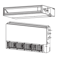
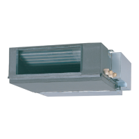
A. CEILING CONCEALED TYPE
3
Outlet air
flow
Drain
hose
Tra p
Arrange the drain hose
lower than this portion
OK
NO
Rise
Supporte
1.5 to 2 m (5 to 6.5 ft)
Air bleeding
OK NO NO
Ris
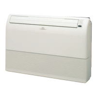
B. FLOOR STANDING CONCEALED TYPE
CAUTION
Install the drain hose so that the control box cover
can be removed for servicing.
In order to prevent water from leaking into the con-
trol box, make sure that the drain hose is well in-
sulated.
After the wiring is connected and installation of
the piping and drain hose is complete, make a seal
around the opening in the wall.
The outside diameter of drain port is 26 mm, use a suitable
drain hose.
TEST RUN
CAUTION
Always turn on the power 12 hours prior to the start
of the operation in order to ensure compressor pro-
tection.
(1) Stop the air conditioner operation.
(2) Press the master control button and the fan control button
simultaneously for 2 seconds or more to start the test run.
Test run displa
(3) Press the start/stop button to stop the test run.
[SELF-DIAGNOSIS]
When the error indication “E:EE” is displayed, follow the following
items to perform the self-diagnosis. “E:EE” indicates an error has
occurred.
1. REMOTE CONTROLLER DISPLAY
(1) Stop the air conditioner operation.
(2) Press the set temperature buttons simultaneously for 5
seconds or more to start the self-diagnosis.
Refer to the following tables for the description of each error
code.
SU
MO
TU
WE
TH FR
SA
Unit number (usually 0)
Error code
EX. Self-dia
nosis
(3) Press the set temperature buttons simultaneously for 5
seconds or more to stop the self-diagnosis.
6
(3) Press the THERMO SENSOR button again for 5 seconds or
more to lock the function. The thermo sensor display flashes
and then remains on when the function is locked.
(4) Make sure that the function is locked.
C. Indoor unit/remote controller setting
(room temperature sensor selection)
The temperature sensor of the indoor unit or the remote controller
can be used to detect the room temperature.
C
Indoor unit
(1) Press the THERMO SENSOR button for 5 seconds or more to
unlock the function. The thermo sensor display flashes and then
disappears when the function is unlocked.
(2) Press the THERMO SENSOR button to select the temperature
sensor of the indoor unit or the remote controller.
4. SETTING THE ROOM TEMPERATURE DE-
TECTION LOCATION
The detection location of the room temperature can be selected
from the following three examples. Choose the detection location
that is best for the installation location.
A. Indoor unit setting (factory setting)
The room temperature is detected by the indoor unit temperature
sensor.
A
Indoor unit
(1)
When the THERMO SENSOR button is pressed, the lock display
flashes because the function is locked at the factory.
B. Remote controller setting
The room temperature is detected by the remote controller tem-
perature sensor.
B
Indoor unit
(1) Press the THERMO SENSOR button for 5 seconds or more to
unlock the function. The thermo sensor display flashes and then
disappears when the function is unlocked.
(2) Press the THERMO SENSOR button.
The thermo sensor display appears.
1. INDOOR UNIT SIDE
(1) Remove the control box cover from the control box.
Control box
Screw
Control box cover
Remove the 4 screws and
remove the control box cover
from the control box.
(2) Cord connection.
• Clamp the connection cord with the cord clamp.
• Connect the connection cord to the terminal board.
• Clamp the remote control cord with nylon clamp.
• Connect the remote control cord to the terminal board.
1
2(N)
3
Cord clamp
Terminal board
Remote control cord
Nylon clamp
Connection cord
123
Drain hose insulation
Unit
Drain hose
Drain hose insulation
Drain hose
Unit
0 mm
@@
ELECTRICAL WIRING
4
2. ROUTING THE REMOTE CONTROLLER WIRES
(1) Install the remote controller wires to the terminals on the top of
the rear case as shown in the following figure.
(2) Fasten the wires with the binder.
(Example)
1. Red
2. White
3. Blac
Binder
3. SETTING THE DIP SWITCHES
When using a battery (memory backup)
ON
ON
OFF
1
2
3
4
5
6
DIP Switch
Change the DIP switch setting to use batteries. (The DIP switch is
not set to use batteries at the factory.)
Change DIP switch No. 6 from OFF to ON.
If batteries are not used, all of the settings stored in memory will be
deleted if there is a power failure.
Temperature
sensor
REMOTE CONTROLLER
SETTING
CAUTION
In order to detect the room tempera-
ture correctly when using the
temperature sensor of the remote
controller, do not install the remote
controller in a place where it will be
exposed to direct sunlight or
directly below the air outlet of the
indoor unit.
When installing the remote controller and cord
near a source of electromagnetic waves, sepa-
rate the remote controller from the source of the
electromagnetic waves and use shielded cord.
Do not touch the remote controller PC board and
PC board parts directly with your hands.
1. INSTALLING THE REMOTE CONTROLLER
(1) Open the operation panel on the front of the remote control-
ler, remove the two screws indicated in the following figure,
and then remove the front case of the remote controller.
DAY OFF
DELETE SET
ENERGY
SAVE
THERMO
SENSOR
SET BACK
DAY
CLOCK ADJUST
Screws
Front case
(back side)
Rear case
Connector
When installing the remote controller, remove the connector
from the front case. The wires may break if the connector is
not removed and the front case hangs down.
When installing the front case, connect the connector to the
front case.
(2) Install the rear case to the wall, etc. with the two tapping
screws.
Refer to the following information to install the remote con-
troller wires.
Front case
Connector
Rear case
Remote controlle
wires
Install the remote controller wires so as not to be direct touched
with your hand.
5
Error code Error contents
Communication error
(indoor unit
remote controller)
Communication error
(outdoor unit
indoor unit)
Room temperature sensor open
Room temperature sensor short-circuited
Indoor heat exchanger temperature sensor open
Indoor heat exchanger temperature sensor short-
circuited
Outdoor heat exchanger temperature sensor
Power source connection error
Float switch operated
Outdoor temperature sensor
Discharge pipe temperature sensor
Model abnormal
Indoor fan abnormal
Outdoor signal abnormal
Outdoor EEPROM abnormal
Compressor temperature sensor
Pressure switch abnormal
IPM error
Compressor cannot operate
Outdoor fan abnormal
HOW TO CONNECT WIRING TO THE TERMINALS
A. For solid core wiring (or F-cable)
(1)
Cut the wire end with a wire cutter or wire-cutting pliers, then strip
the insulation to about 25 mm (15/16”) of expose the solid wire.
(2)
Using a screwdriver, remove the terminal screw(s) on the terminal board.
(3) Using pliers, bend the solid wire to form a loop suitable for
the terminal screw.
(4)
Shape the loop wire properly, place it on the terminal board and
tighten securely with the terminal screw using a screwdriver.
B. For strand wiring
(1)
Cut the wire end with a wire cutter or wire-cutting pliers, then strip
the insulation to about 10 mm (3/8”) of expose the strand wiring.
(2)
Using a screwdriver, remove the terminal screw(s) on the terminal board.
(3) Using a round terminal fastener or pliers, securely clamp a
round terminal to each stripped wire end.
(4) Position the round terminal wire, and replace and tighten
the terminal screw using a screwdriver.
HOW TO FIX CONNECTION CORD AND
POWER CABLE AT THE CORD CLAMP
After passing the connection cord and power cable through the
insulation tube, fasten it with the cord clamp.
Loop
Strip 25 mm (15/16
,,
)
Strip 10 mm (3/8
,,
)
Screw with
special washer
Screw with
special washer
Round
terminal
Round
terminal
Round terminal
Wire
Wire
Insulation
Terminal
board
A. Solid wire
B. Strand wire
Insulation tube
Insulation
tube
Cord clamp
Use VW-1, 0.5 to 1.0 mm thick, PVC tube as the insulation tube.
WARNING
Before starting work, check that power is not be-
ing supplied to the indoor unit and outdoor unit.
Match the terminal board numbers and connection cord
colors with those of the outdoor unit.
Erroneous wiring may cause burning of the electric parts.
Connect the connection cords firmly to the termi-
nal board. Imperfect installation may cause a fire.
Always fasten the outside covering of the con-
nection cord with the cord clamp. (If the insulator
is chafed, electric leakage may occur.)
Always connect the ground wire.
CAUTION
Tighten the indoor unit connection cord (to the out-
door unit) and power supply indoor and outdoor
unit terminal board connections firmly with the ter-
minal board screws. Faulty connection may cause
a fire.
If the indoor unit connection cord (to the outdoor
unit) and power supply are wired incorrectly, the
air conditioner may be damaged.
Wire the indoor unit connection cord (to the out-
door unit) by matching the numbers of the out-
door and indoor units terminal board numbers as
shown in terminal label.
Ground both the indoor and outdoor units by at-
taching a ground wire.
Unit shall be grounded in compliance with the ap-
plicable local and national codes.
2. Floor standing concealed/ceiling
concealed select switch
(1) The DIP switches were set for use as a ceiling concealed type
at the factory.
(2) The following changes must be made to the settings if the unit
is to be used as a floor standing concealed type.
(3) Changing the settings for the electrical circuits.
DIP Switch 1 (SW1) on the printed circuit board inside the elec-
tric component box must be set as follows.
Rotary switch
DIP switch
[SW1]
Indoor unit PC board
SW1 SW1
Ceiling concealed type Floor standing
concealed type
AIR FLOW SETTING
Static range is 0 to 40 Pa.
If static pressure is over 20 Pa, we recommend High static mode.
Change the High static and Normal mode. If select the High static
mode, air flow increases.
About 9000 BTU model and 22000 BTU model, High static mode
and normal mode are same air flow.
The air flow is set according to the DIP switch settings in the follow-
ing tables.
[12000 - 18000 BTU/h models]
Fan mode
Normal mode (0
Pa 20)
High static pressure mode (20 < Pa 40)
CAUTION
Do not set any switches other than those specified
in this sheet. The air conditioner may not operate
correctly if any switches other than those specified
are changed.
7
DIP-SW4
12 3
— OFF OFF
— ON OFF
SPECIAL INSTALLATION
METHODS
CAUTION
When setting the rotary switch and DIP switches,
do not touch any other parts on the circuit board
directly with your bare hands.
Be sure to turn off the main power.
1. GROUP CONTROL SYSTEM
A number of indoor units can be operated at the same time using a
single remote controller.
(1) Wiring method (indoor unit to remote controller)
1 2 3 1 2 3 1 2 3
1 2 3
1 2 3
Indoor unit
No.
0
Indoor unit
No.
1
Indoor unit
No.
2
Indoor unit
No.
3
Remote controller wire
Remote
controller
(2) Rotary switch setting (indoor unit)
Set the unit number of each indoor unit using the rotary switch
on the indoor unit circuit board.
The rotary switch is normally set to 0.
(3)
DIP switch setting (remote controller)
Change DIP switch No. 3 on the remote controller from OFF to ON.
Indoor unit
Rotary Switch
Remote controller
DIP Switch
ONOFF
1
2
3
4
5
6
ON
1
2
3
O
F
F
SW 4
1
2
3
O
F
F
SW 1
Indoor unit PC board
DIP switch
(SW4)
Indoor unit
PC board
8
3. AUTO RESTART
• When the air conditioner power was temporarily turned off by a
power failure etc., it restarts automatically after the power recov-
ers.
(Operated by setting before the power failure)
The auto restart function can be canceled.
(1) DIP switch setting (indoor unit)
Change the DIP switch (SW1-1) on the indoor unit circuit board
from ON to OFF. The auto restart function will be canceled.
Indoor unit
DIP Switch
O
F
F
1
2
3
OFF
SW1
O
F
F
1
2
3
SW4
PART NO. 9374815012-02
NO.
SW state
Detail
OFF ON
1 ✽
Dual remote controller
2 ✽
setting
3
One unit
✽ Multiple unit Group control setting
4
Heat & Cool model
Cooling only model
Model setting
5 Invalidity Validity ✽
Auto changeover setting
6 Invalidity✽ Validity
Memory backup setting
NO.
SW state
Detail
OFF ON
1 Invalidity Validity ✽ Auto restart setting
2 ——✽
Temperature correction
3 ——✽
setting for heating
1 — ✽ —
Remote controller setting
2 — ✽ —
Air flow setting
3 — ✽ —
DIP-Switch 1
● Indoor unit
● Remote controller
[DIP-SWITCH SETTING]
✽ : Factory setting
DIP-Switch 4
DIP-Switch
2.
DUAL REMOTE CONTROLLERS (OPTIONAL)
Two separate remote controllers can be used to operate the indoor
units.
(1) Wiring method (indoor unit to remote controller)
1 2 3
1 2 3
1 2 3
Remote
controller
wire
Remote
controller
Master
unit
Slave
unit
Indoor unit
(2) DIP switch setting (remote controller)
Set the remote controller DIP switch Nos. 1 and 2 according to
the following table.
Number of
remote
controllers
Master unit
1 (Normal)
2 (Dual)
ON
OFF
OFF
OFF
DIP-SW No. 1
DIP-SW No. 2
Remote
controller
ONOFF
1
2
3
4
5
6
DIP Switch
Number of
remote
controllers
Slave unit
1 (Normal)
2 (Dual)
–
ON
–
ON
DIP-SW No. 1 DIP-SW No. 2
00
01
02
03
04
05
06
08
09
0A
0c
11
12
13
14
15
16
17
1A
1b
NOTES
If the function to change the temperature sensor is used as shown
in examples A and B (other than example C), be sure to lock the
detection location. If the function is locked, the lock display
will flash when the THERMO SENSOR button is pressed.
9374815012-02B2back 6/7/05, 3:49 PM1
 Loading...