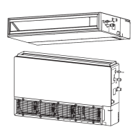
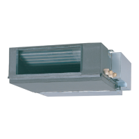
Duct Type
SPLIT TYPE AIR CONDITIONER
INSTALLATION INSTRUCTION
SHEET
(PART NO. 9374318063)
Indoor unit is an appliance not accessible to the general public.
For authorized service personnel only.
This mark indicates procedures which, if improperly performed, might lead to the death or
serious injury of the user.
This mark indicates procedures which, if improperly performed, might possibly result in
personal harm to the user, or damage to property.
This air conditioner uses new refrigerant HFC (R410A).
The basic installation work procedures are the same as conventional refrigerant models.
However, pay careful attention to the following points:
Since the working pressure is 1.6 times higher than that of conventional refrigerant models, some of the
piping and installation and service tools are special. (See the table below.)
Especially, when replacing a conventional refrigerant model with a new refrigerant R410A model, always
replace the conventional piping and flare nuts with the R410A piping and flare nuts.
Models that use refrigerant R410A have a different charging port thread diameter to prevent erroneous
charging with conventional refrigerant and for safety. Therefore, check beforehand. [The charging port thread
diameter for R410A is 1/2 UNF 20 threads per inch.]
Be more careful that foreign matter (oil, water, etc.) does not enter the piping than with conventional refrig-
erant models. Also, when storing the piping, securely seal the openings by pinching, taping, etc.
When charging the refrigerant, take into account the slight change in the composition of the gas and liquid
phases, and always charge from the liquid phase side whose composition is stable.
When moving, if the compressor stops during pump down, close the valve immediately.
Special tools for R410A
Copper pipes
It is necessary to use seamless copper pipes and it is desirable that the amount of residual oil is less than 40 mg/10m. Do not use copper
pipes having a collapsed, deformed or discolored portion (especially on the interior surface). Otherwise, the expansion valve or capillary
tube may become blocked with contaminants.
As an air conditioner using R410A incurs pressure higher than when using
conventional refrigerant, it is necessary to choose adequate materials.
Thicknesses of copper pipes used with R410A are as shown in Table. Never
use copper pipes thinner than that in the table even when it is available on
the market.
Thicknesses of Annealed Copper Pipes
Refrigerant
R410A
WARNING
CAUTION
Thickness
0.80 mm
1.00 mm
Pipe outside diameter
9.52 mm (3/8 in)
15.88 mm (5/8 in)
Contents of change
Pressure is high and cannot be measured with a conventional gauge. To prevent erroneous mixing
of other refrigerants, the diameter of each port has been changed.
It is recommended the gauge with seals –0.1 to 5.3 MPa (–76 cmHg to 53 kgf/cm
2
) for high pressure.
–0.1 to 3.8 MPa (–76 cmHg to 38 kgf/cm
2
) for low pressure.
To increase pressure resistance, the hose material and base size were changed.
A conventional vacuum pump can be used by installing a vacuum pump adapter.
Special gas leakage detector for HFC refrigerant R410A.
Tool name
Gauge manifold
Charge hose
Vacuum pump
Gas leakage detector
STANDARD PARTS
The following installation parts are furnished. Use them as required.
INDOOR UNIT ACCESSORIES
Name and Shape
Hanger
Special nut A
(large flange)
Special nut B
(small flange)
Coupler heat
insulation (large)
Coupler heat
insulation (small)
Q’ty
4
4
4
1
1
Application
For suspending the indoor
unit from ceiling
For suspending the indoor
unit from ceiling
For indoor side pipe joint
(large pipe)
For indoor side pipe joint
(small pipe)
Name and Shape
Binder
Remote
controller
Tapping screw
(flush heads)
Remote controller cord
Drain hose insulation
Q’ty
1
(large)
1
(small)
1
2
1
1
Application
For fixing the drain hose
For fixing the remote
controller cord
For installing the remote
controller
For connecting the remote
controller
Insulates the drain hose
and vinyl hose
OPTIONAL PARTS
When connecting the square duct and round duct, use the optional square flange or round flange and flexible duct.
Square flange Round flange
Model name : UTD–SF045T (P/N 9098180007) Model name : UTD–RF204 (P/N 9093160004)
Flexible duct Long-life filter
Model name : UTD–RD202 (P/N 9074165004) Model name : UTD–LF25NA (P/N9079892004)
Simple remote controller
Model name : UTB–YPB (P/N9077582006)
Remote sensor
Model name : UTD–RS100 (P/N9072619004)
40 mm
204 mm
1065 mm
ø235 mm
ø195 mm
ø205 mm
85 mm
ø225 mm
ø200 mm
L 2 m
507 mm
239 mm
For authorized service personnel only.
WARNING
For the air conditioner to operate satisfactorily, install it as outlined in this installation instruction sheet.
Connect the indoor unit and outdoor unit with the air conditioner piping and cords available standards parts.
This installation instruction sheet describes the correct connections using the installation set available
from our standard parts.
Installation work must be performed in accordance with national wiring standards by authorized personnel
only.
If refrigerant leaks while work is being carried out, ventilate the area. If the refrigerant comes in contact with
a flame, it produces a toxic gas.
Do not use an extension cord.
Do not turn on the power until all installation work is complete.
CAUTION
This installation instruction sheet describes how to install the indoor unit only.
To install the outdoor unit, refer to the installation instruction sheet included with the outdoor unit.
•Be careful not to scratch the air conditioner when handling it.
• After installation, explain correct operation to the customer, using the operating manual.
• Let the customer keep this installation instruction sheet because it is used when the air conditioner is serv-
iced or moved.
SELECTING THE MOUNTING POSITION
WARNING
Install at a place that can withstand the weight of the indoor and outdoor units and install positively so that the
units will not topple or fall.
CAUTION
Do not install where there is the danger of combustible gas leakage.
Do not install the unit near heat source of heat, steam, or flammable gas.
If children under 10 years old may approach the unit, take preventive measures so that they cannot reach the
unit.
Decide the mounting position with the customer as follows:
INDOOR UNIT
(1) Install the indoor unit on a place having a sufficient strength so that it withstand against
the weight of the indoor unit.
(2) The inlet and outlet ports should not be obstructed; the air should be able to blow all
over the room.
(3) Leave the space required to service the air conditioner.
(4) Install the unit where the drain pipe can be easily installed.
(5) Providing as much space as possible between the indoor unit and the ceiling will
make work much easier.
(6) If installing in a place where its humidity exceeds 80%, use heat insulation to prevent
condensation.
Maintenance hole dimension
It shall be possible to install and remove the control box. It shall be possible to install and remove the control box, fan
units and filter.
300 mm
or more
150 mm
or more
Maintenance hole
Control box
500 mm
500 mm
300 mm
100 mm
Maintenance hole
Intake panel
500 mm
1550 mm
300 mm
100 mm
Control box
INSTALLATION
PROCEDURE
Install the air conditioner as follows:
CAUTION
Install the drain hose in accordance with the instruc-
tions in this installation instruction sheet and keep
the area warm enough to prevent condensation.
Problems with the piping may lead to water leaks.
NOTE: INSTALL THE DRAIN HOSE
• Install the drain hose with downward gradient (1/50 to
1/100) and so there are no rises or traps in the hose.
• Use general hard polyvinyl chloride pipe (VP25) [outside diam-
eter 38mm] and connect it with adhesive (polyvinyl chloride) so
that there is no leakage.
• When the hose is long, install supporters.
• Do not perform air bleeding.
• Always heat insulate the indoor side of the drain hose.
Drain
hose
Outlet
air flow
Arrange the drain hose lower
than this portion
Tra p
OK
NO
Ris
Supporter
1.5 to 2 m
Air bleeding
• When the unit is shipped from the factory, the drain port is on
the left side (control box side).
•When using the drain port on the right side of the unit, reinstall
the drain cap to the left side drain port.
Drain port
Drain cap Nylon fastener
CAUTION
Always check that the drain cap is installed to the
unused drain port and is fastened with the nylon
fastener.
If the drain cap is not installed, or is not sufficiently
fastened by the nylon fastener, water may drip dur-
ing the cooling operation.
• Cut the drain hose insulation at a position approximately 30mm
from the end with cutters, etc.
• Stick the large drain hose insulation at the drain hose installa-
tion side.
• Stick the small drain hose insulation at the drain cap side.
Drain hose
insulation
(large)
Drain hose
unit
unit
Drain hose
insulation
(large)
Drain hose
0 mm (0")
Drain hose insulation (small)
Unit
Drain ca
Drain hose
insulation
(small)
Unit
0 mm (0")
4. INTAKE DUCT CONNECTION
Follow the procedure in the following figure to the ducts.
1015 mm
240mm
The air inlet duct can be changed by replacing the intake grille
and flange.
For the bottom air intake, follow the procedure of → for
installation.
(The factory setting is back air intake.)
①
(1) Square duct
CAUTION
When air is taken in from the bottom side, the oper-
ating sound of the product will easily eater the room.
Install the product and intake grilles where the af-
fect of the operating sound is small.
CAUTION
If an intake duct is installed, take care not to
damage the temperature sensor (the tempera-
ture sensor is attached to the intake port flange).
Be sure to install the air inlet grille and the air
outlet grille for air circulation. The correct tem-
perature cannot be detected.
Unit
Air Outlet Grille Air inlet Grille
(Room)
Grills must be fixed so that man cannot touch
indoor unit fan, and cannot be removed by only
hand operation without tool.
Be sure to install the air filter in the air inlet. If
the air filter is not installed, the heat exchanger
may be clogged and its performance may de-
crease.
6. FRESH AIR INTAKE
(Processing before use)
(1) When taking in fresh air, cut a slit shaped cabinet in the left
side of the outer case with nippers.
Cut
Cut
Cabinet (iron plate) Square hole
CAUTION
When removing the cabinet (iron plate), be care-
ful not to damage the indoor unit internal parts
and surrounding area (outer case).
When processing the cabinet (iron plate), be
careful not to injure yourself with burrs, etc.
(2) Install the round flange (option parts) to the fresh air intake.
Round duct
(3) Connect the duct to the round flange.
(4) Seal with a band and vinyl tape, etc. so that air does not leak
from the connection.
Duct
450 mm
170 mm
30 mm
170 mm
420 mm
170 mm
30 mm
Cut line
5. OUTLET DUCT CONNECTION
Duct installation pattern ( CUT PART)
When using as a square duct
(1) Cut the slit seam with a cutter.
(2) Turn up the insulation around the points to be cut according
to the outlet port shape working points so that the insulation
does not stick out at the part.
Cut Cut
Cut
Cut
(3) Cut with nippers and remove the sheet metal.
(4) Since there is a slit in the insulation, use radio pliers, tweez-
ers, etc. to stretch the screw hole part used when installing
the round flange and square flange when connecting the duct.
(
2) Round duct outlet ×4
(This is the factory setting.)
Slide the unit in the arrow direction and fasten it.
Bolt Strength 9.81 to 14.71 N·m (100 to 150 kgf·cm)
WARNING
Fasten the unit securely with special nuts A and B.
2. LEVELING
Base vertical direction leveling on the unit (right and left).
Level meter
AIR
AIR
Base horizontal direction leveling on top of the unit.
0-5 mm
Drain hose
Give a slight tilt to the side to which the drain hose is connected.
The tilt should be in the range of 0 mm to 5 mm
3. INSTALLING DRAIN HOSE
Install the drain hose according to the measurements given in the
following figure.
Liquid pipe
Drain pipe
Gas pipe
32 mm
66 mm
114 mm
240 mm
ø 38 mm (O.D.)
Drain pipe
ø 38 mm (O.D.)
The drain cap is attached
at the factory setting.
32 mm
240 mm
(Left side)
(Left side)
(Right side)
Hanging bolt M10
(Obtained locally)
Special nut A
Washer
(Obtained locally)
Special nut B
Hanger
1
INDOOR UNIT
INSTALLATION
RECOMMENDED RANGE OF
EXTERNAL STATIC PRESSURE
30Pa to 150Pa
WARNING
Install the air conditioner in a location which can
withstand a load of at least five times the weight
of the main unit and which will not amplify sound
or vibration.
If the installation location is not strong enough,
the indoor unit may fall and cause injuries.
If the job is done with the panel frame only, there
is a risk that the unit will come loose. Please
take care.
CAUTION
For installation, refer to the technical data.
1. INSTALLING THE HANGERS
WARNING
When fastening the hangers, make the bolt posi-
tions uniform.
Hanging bolt installation diagram.
(Example)
(Top side)
(Left side)
The distance of is adjustable according to the place of the
hanging bolts.
(MAX : 550 mm, MIN : 410 mm)
740 mm
1135
mm
1177
mm
270 mm
AIR
AIR
477 mm
ELECTRICAL REQUIREMENT
• Install the disconnect device with a contact gap of at least 3 mm nearby the units.
(Both indoor unit and outdoor unit)
• Always use H07RN-F or equivalent to the connection cord.
CONNECTING PIPE REQUIREMENT
CAUTION
Install heat insulation around both the gas and liquid pipes. Failure to do so may cause water leaks.
Use heat insulation with heat resistance above 120 °C. (Reverse cycle model only)
In addition, if the humidity level at the installation location of the refrigerant piping is expected to exceed 70%,
install heat insulation around the refrigerant piping. If the expected humidity level is 70-80%, use heat insulation
that is 15 mm or thicker and if the expected humidity exceeds 80%, use heat insulation that is 20 mm or thicker.
If heat insulation is used that is not as thick as specified, condensation may form on the surface of the insula-
tion. In addition, use heat insulation with heat conductivity of 0.045 W/(m·K) or less (at 20 °C).
• Use pipe with water-resistant heat insulation.
• Electric wire size :
Small
Large
9.52 mm (3/8 in.)
15.88 mm (5/8 in.)
Diameter
MAX.
MIN.
Connection cord (mm
2
)
2.5
1.5
9374318063B2front 05.2.9, 12:091
 Loading...