En-14
■Operation behavior
*If function setting “60” is set to “00”
Function setting Status Output voltage
60
00
Stop 0V
Operation DC 12 V
09
Normal 0V
Error DC 12 V
10
Indoor unit fan stop 0V
Indoor unit fan operation DC 12 V
11
External heater OFF 0 V
External heater ON DC 12V
4.2.3. Connection methods
■
Wire modifi cation
• Remove insulation from wire attached to wire kit connector.
• Remove insulation from locally purchased cable. Use crimp type insulated butt
connector to join fi eld cable and wire kit wire.
• Connect the wire with connecting wire with solder.
IMPORTANT:
Be sure to insulate the connection between the wires.
Locally purchased
Option parts
External output wire
Solder and insulate the connected parts.
• Connecting wires to the terminals.
Use ring terminals with insulating sleeves to connect to the terminal block.
• Connection terminals and wiring arrangement (Refer to “4.6. Other optional parts”)
4.3. Remote sensor (Optional parts)
4.3.1. Connection method
• Remove the existing connector and replace it with the remote sensor connector (ensure
that the correct connector is used).
• The original connector should be insulated to ensure that it does not come into contact
with other electrical circuitry.
• Connection terminals and wiring arrangement. (Refer to “4.6. Other optional parts”)
4.3.2. Setting for room temperature correction
When a remote sensor is connected, set the function setting of indoor unit as indicated
below.
• Function Number “30”:
Set the Setting Number to “00”. (Default)
• Function Number “31”:
Set the Setting Number to “02”.
* Refer to “6. FUNCTION SETTING” for details about Function number and Setting
value
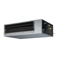
4.4. IR receiver unit (Optional parts)
• For the installation method, please refer to the installation manual of IR receiver unit.
4.4.1. Connection method
• Use 7 pins for receiver unit cable.
• At fi rst, connect the receiver unit cable to the controller PCB.
• Attach the core that comes between controller PCB and the clamp.
• Connection terminals and wiring arrangement. (Refer to “4.6. Other optional parts”).
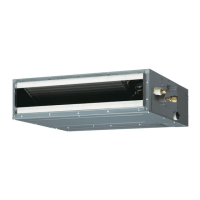
4.5. Auto louver grille (Optional parts)
4.5.1. Connection method
• Wiring arrangement
Y1 Y2
TO REMOTE CONTROL UNIT Ex IN
Y3 1 2
12 3
CN11
Controller PCB
DIP SW 101
( " 2 " : ON)
CAUTION
To protect the cable insulation after opening a knockout hole, remove any burrs from
the edge of the hole.
(b) Bushing
(accessories of
optional parts)
Cable tie
(medium, accessories)
Auto louver grille cable
(c) Block gaps with insulation
(accessories)
(a) Opening this
knockout hole
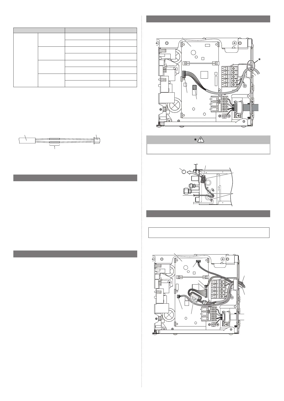
4.6. Other optional parts
4.6.1. Connection method
• Connection terminals and wiring arrangement
In following fi gure, all the possible connections are done for description.
In actual installation, connections will differ according to each installation requirements.
Y1 Y2
TO REMOTE CONTROL UNIT Ex IN
Y3 1 2
12 3
CN8
CN65
CN47
CN48
Controller PCB
External output
External input
Core
9374342532_IM.indb 149374342532_IM.indb 14 2018/12/11 10:11:352018/12/11 10:11:35
 Loading...