En-5
2.5. Optional parts
Refer to each installation manual for the method of installing optional parts.
Parts name Model No. Application
Wired remote controller
UTY-RNR
Z
For air conditioner operation
(2-wired type)
UTY-RLR
UTY-RVN
M
For air conditioner operation
(3-wired type)
UTY-RNN
M
Simple remote controller
UTY-RSR
For air conditioner operation
(2-wired type)
UTY-RHR
UTY-RSN
M
For air conditioner operation
(3-wired type)
IR receiver unit UTY-LBT
M For the wireless remote controller
Remote sensor unit UTY-XSZX Room temperature sensor
Auto louver grille kit
UTD-GXTA-W
Air outlet grille with outo louver
(07, 09,12,14 models)
UTD-GXTB-W
Air outlet grille with outo louver
(18 model)
External connect kit
PCB terminal For control input port
UTY-XWZXZG For control output port
W-LAN interface UTY-TFSXZ1 For wireless LAN control
3. INSTALLATION WORK
WARNING
Do not move the appliance by holding the indoor unit pipes.
(The stress applied to the pipe joints may cause the fl ammable gas to leak during
operation.)
3.1. Selecting an installation location
Especially, the installation place is very important for the split type air conditioner because it
is very diffi cult to move from place to place after the fi rst installation.
WARNING
Select installation locations that can properly support the weight of the indoor. Install
the units securely so that they do not topple or fall.
CAUTION
• Do not install the unit in the following areas:
- Area with high salt content, such as at the seaside. It will deteriorate metal parts,
causing the parts to fail or the unit to leak water.
- Area fi lled with mineral oil or containing a large amount of splashed oil or steam,
such as a kitchen. It will deteriorate plastic parts, causing the parts to fail or the
unit to leak water.
- Area where is close to heat sources.
- Area that generates substances that adversely affect the equipment, such as
sulfuric gas, chlorine gas, acid, or alkali. It will cause the copper pipes and brazed
joints to corrode, which can cause refrigerant leakage.
- Area that can cause combustible gas to leak, contains suspended carbon fi bers or
fl ammable dust, or volatile in fl ammables such as paint thinner or gasoline.
- If gas leaks and settles around the unit, it can cause a fi re.
- Area where animals may urinate on the unit or ammonia may be generated.
• Do not use the unit for special purposes, such as storing food, raising animals, grow-
ing plants, or preserving precision devices or art objects. It can degrade the quality
of the preserved or stored objects.
• Install the unit where drainage does not cause any trouble.
• Install the indoor unit, outdoor unit, power supply cable, transmission cable, and
remote control cable at least 1 m away from a television or radio receivers. The
purpose of this is to prevent TV reception interference or radio noise.
(Even if they are installed more than 1 m apart, you could still receive noise under
some signal conditions.)
• If children under 10 years old may approach the unit, take preventive measures so
that they cannot reach the unit.
• Decide the mounting position with the customer as follows:
(1) Install the indoor unit in a location having suffi cient strength to support the weight of
the indoor unit.
(2) The inlet and outlet ports should not be obstructed; the air should be able to blow all
over the room.
(3) Leave the space required to service the air conditioner.
(4) Locate where the air can be distributed evenly throughout the room by the unit.
(5) Install the unit where connection to the outdoor unit is easy.
(6) Install the unit where the connection pipe can be easily installed.
(7) Install the unit where the drain pipe can be easily installed.
(8) Install the unit where noise and vibration is not amplifi ed.
(9) Take servicing, etc., into consideration and leave the spaces. Also install the unit
where the fi lter can be removed.
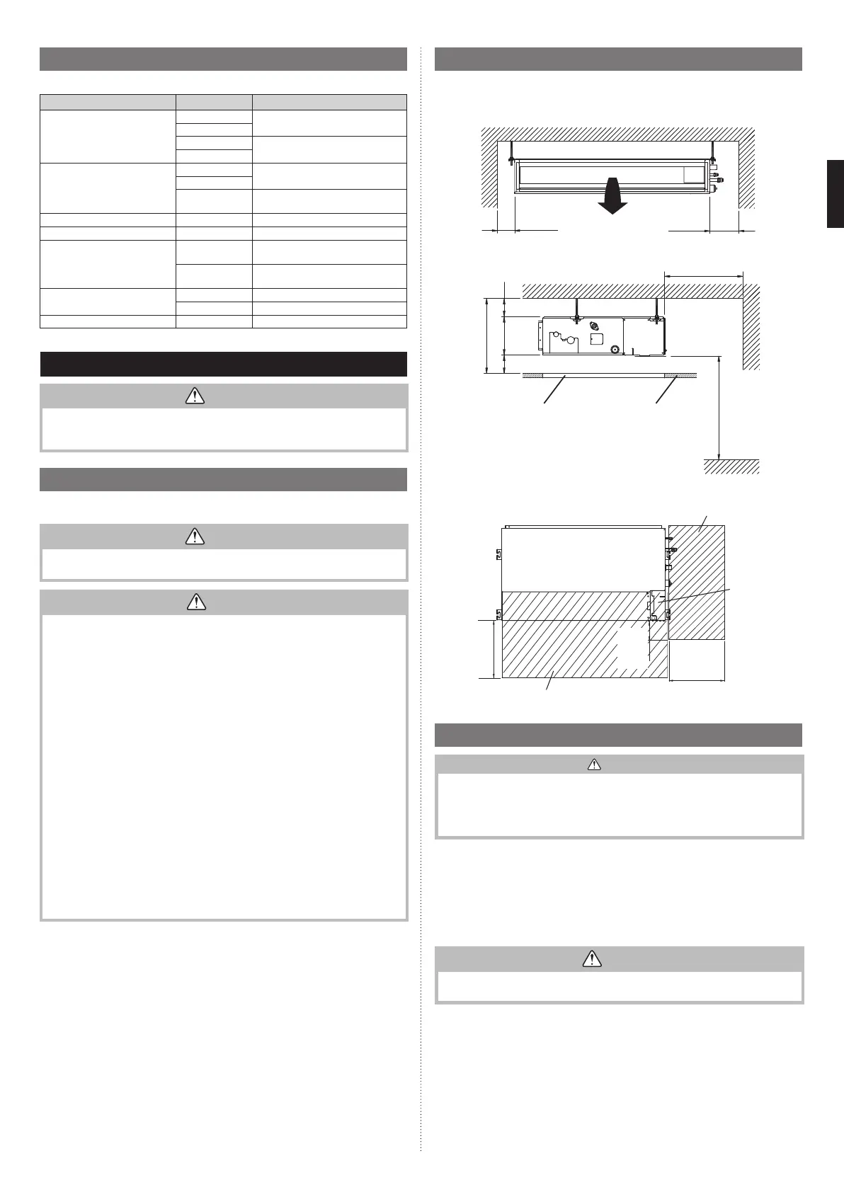
3.2. Installation dimensions
Provide a Service access for inspection purposes.
Do not place any wiring or illumination in the service space, as they will impede service.
Left
side
Strong and durable ceiling
Indoor unit
Right
side
150 mm
or more
400 mm
or more
Service access Ceiling
2500 mm or more
(When no ceiling)
Floor
240 mm or more
20 mm or more
20 mm or more
300 mm or more
Adjust the wind direction in the room depending on the shape of blow out opening.
Service access
Unit
Control
box
400 mm
or more
100 mm
or more
300 mm
or more
Service space
3.3. Installing the unit
WARNING
• Install the air conditioner in a location which can withstand a load do at least 5 times
the weight of the main unit and which will not amplify sound or vibration. If the instal-
lation location is not strong enough, the indoor unit may fall and cause injuries.
• If the work is done with the panel frame only, there is a risk that the unit will come
loose. Please take care.
3.3.1. Unit installation example
■
Connect the locally purchased duct:
(1) Inlet side
• Connect the duct to the locally purchased inlet fl ange.
• Connect the fl ange to the body with the locally purchased tapping screws.
• Wind the inlet fl ange connecting to the duct with the aluminum tape etc. to avoid the
air discharge.
CAUTION
When the duct is connected to inlet side, remove contained fi lter and surely attach
locally purchased fi lter at inlet opening.
(2) Outlet side
• Connect the duct with adjusting inside of outlet fl ange.
• Wind the outlet fl ange connecting to the duct with the aluminum tape etc. to avoid the
air discharge.
• Insulate the duct to avoid the dew condensation.
9374342532_IM.indb 59374342532_IM.indb 5 2018/12/11 10:11:302018/12/11 10:11:30
 Loading...