En-6
CAUTION
• Check that duct work does not exceed the range of external static pressure of equip-
ment.
• Make sure to insulate ducts to avoid the dew condensation.
• Make sure to insulate between ducts and walls if metal ducts are used.
•
Please explain handling and washing methods of locally purchased materials to the
customer.
• To prevent people from touching the parts inside the unit, be sure to install grilles on
the inlet and outlet ports. The grilles must be designed in such a way that cannot be
removed without tools.
• When connecting the duct to the outlet port of the indoor unit, be sure to insulate the
outlet port and the installation screws to prevent water from leaking around the port.
• Set the static pressure outside the unit to 90 Pa or less (the allowable range is be-
tween 0 and 90 Pa.)
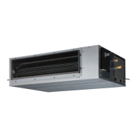
■
Replace the cover as follows:
• Remove the screws, and then remove cover and fan guard.
• Install the cover with the screws as shown in the illustration below.
Model Screw
07, 09, 12, 14 9
18 11
Screw
Cover
Fan guard
Side inlet - Side outlet
Insulation material (Locally purchased)
Aluminum tape
Flange (Locally purchased)
Air
Duct
(Locally purchased)
Air
Intake grille
(Locally
purchased)
Side inlet - Side outlet (Duct)
Insulation material (Locally purchased)
Aluminum tape
Aluminum tape
Tapping screw for
fl ange connection
(M4 x 10mm /
Locally
purchased)
Flange (Locally purchased)
Flange (Locally purchased)
Air
Duct
(Locally purchased)
Air
Intake grille
(Locally purchased)
Bottom inlet - Side outlet
Duct (Locally purchased)
Intake grille (Locally purchased)
Air
Air
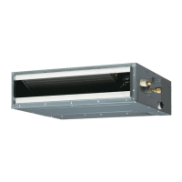
Outlet side
Inlet side
07, 09, 12,14 models 18 model
A 650 mm 850 mm
B P200×2=400 mm P200×3=600 mm
CAUTION
• Be sure to install the air inlet grille and the air outlet grille for air circulation. The cor-
rect temperature cannot be detected.
• Grills must be fi xed so that man cannot touch indoor unit fan and exchanger, and
cannot be removed by only hand operation without tool.
• Be sure to install the air fi lter in the air inlet.
If the air fi lter is not installed, the heat exchanger may be clogged and its perfor-
mance may decrease.
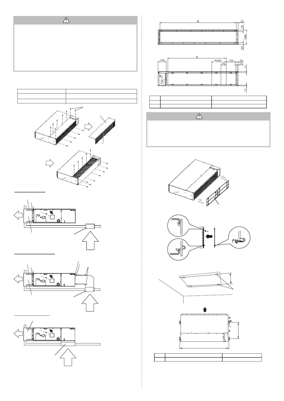
3.3.2. Install the fi lters
• Install the fi lters to the unit.
Filter (accessories)
Unit
Filter
3.3.3. Position the ceiling hole and hanging bolts
• Using the installation template, drill holes for bolts (4 holes).
Drilling position
for bolts
Installation template
(accessory)
A
Air
377 mm
07, 09, 12, 14 models 18 model
A 734 mm 934 mm
9374342532_IM.indb 69374342532_IM.indb 6 2018/12/11 10:11:302018/12/11 10:11:30
 Loading...