Trouble shooting 36
Forecast of Cause:
Check Point 2 : Check external cause at Indoor and Outdoor (Voltage drop or Noise)
Check Point 1 : Check indoor and outdoor installation condition
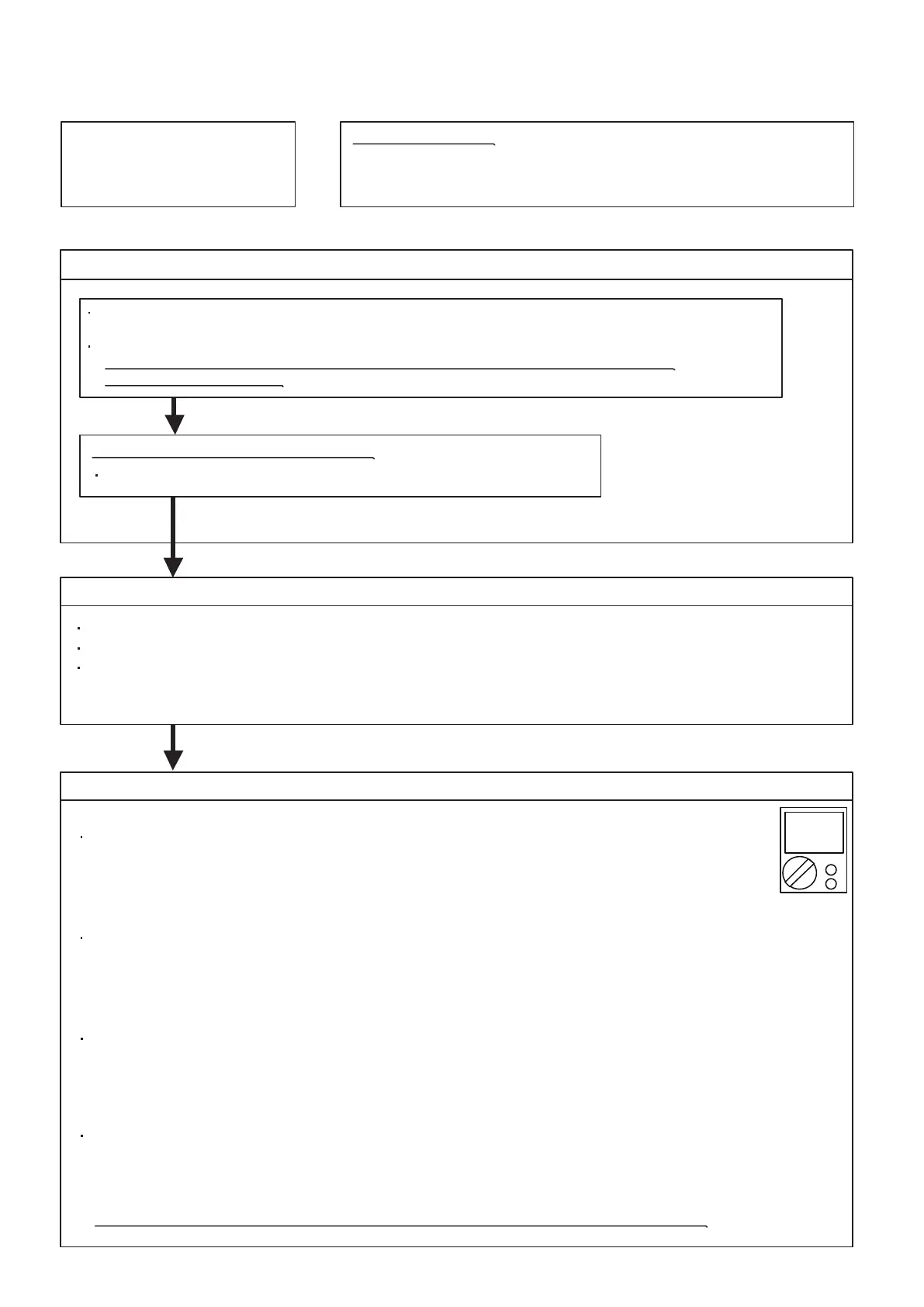
Check Point 3 : Check Wired Remote Controller and Controller PCB
OK
OK
OK
No Operation (Power is ON)
1. Setting/ Connection failure 2. External cause
3. Electrical Component defective
Indoor Unit - Check incorrect wiring between Indoor Unit - Remote Control.
Or, check if there is an open cable connection.
Are these Indoor Unit, Outdoor Unit, and Remote Control suitable model numbers to connect?
>> If there is some abnormal condition, correct it by referring to Installation manual and
Data & Technical Manual.
Turn off Power and check/ correct followings.
Is there loose or removed communication line of Indoor Unit and Outdoor Unit?
Instant drop ----- Check if there is a large load electric apparatus in the same circuit.
Momentary power failure ----- Check if there is a defective contact or leak current in the power supply circuit.
Noise ----- Check if there is any equipment causing harmonic wave near electric line.
(Neon bulb or electric equipment that may cause harmonic wave)
Check the complete insulation of grounding.
>> If the symptom does not change by above Check 1, 2, 3, replace Main PCB of Outdoor unit.
02-37
DC
Check Voltage at CN300 of Controller PCB. (Terminal 1-3, Terminal 1-2)
(Power supply for the Remote Control)
Check Voltage at CN300 (Terminal 1-2) of UTY-TWRXZ2 (Communication kit).
(Power supply to Remote control)
For AS* G __ KGTB
>> If it is DC12V, Remote control is failure. (Controller PCB is normal) >> Replace Remote control
>> If it is DC 0V, Controller PCB is failure. (Check Remote control once again) >> Replace Controller PCB
Check Voltage at CNC01 (Terminal 1-3) of UTY-TWBXF2 (Communication kit).
(Power supply to Remote control)
For AS* G __ KMTB
For AR type
For AU type
>> If it is DC13V, Remote control is failure. (Controller PCB is normal) >> Replace Remote control
>> If it is DC 0V, Controller PCB is failure. (Check Remote control once again) >> Replace Controller PCB
>> If it is DC13V, Remote control is failure. (Controller PCB is normal) >> Replace Remote control
>> If it is DC 0V, Controller PCB is failure. (Check Remote control once again) >> Replace Controller PCB
Check Voltage at CN14 of Controller PCB. (Terminal 1-3, Terminal 1-2)
(Power supply for the Remote Control)
>> If it is DC12V, Remote control is failure. (Controller PCB is normal) >> Replace Remote control
>> If it is DC 0V, Controller PCB is failure. (Check Remote control once again) >> Replace Controller PCB
 Loading...