02-04
Trouble shooting 3
INDOOR UNIT Error Method:
Detective Actuators:
Detective details:
Forecast of Cause:
OK
Indicate or Display:
1. Connection failure 2. Wired Remote Controller failure 3. Controller PCB failure
Check Point 1 : Check the connection of terminal
After turning off the power.
Check & correct the followings.
Upon receiving the signal more than 1 time from Wired Remote or other Indoor
unit, but the same signal has not been received more than 1 minute
(3 Wire type), 2.5 minute (2 Wire type)
Wired Remote Controller
Communication Error
Indoor unit Controller PCB
Wired Remote Controller
Error code : 12 Outdoor unit : No indication
Check the connection of terminal berween Wired Remote Controller and indoor unit,
and check if there is a disconnection of the cable.
Check Point 1-2 : Check Wired Remote Controller and Controller PCB
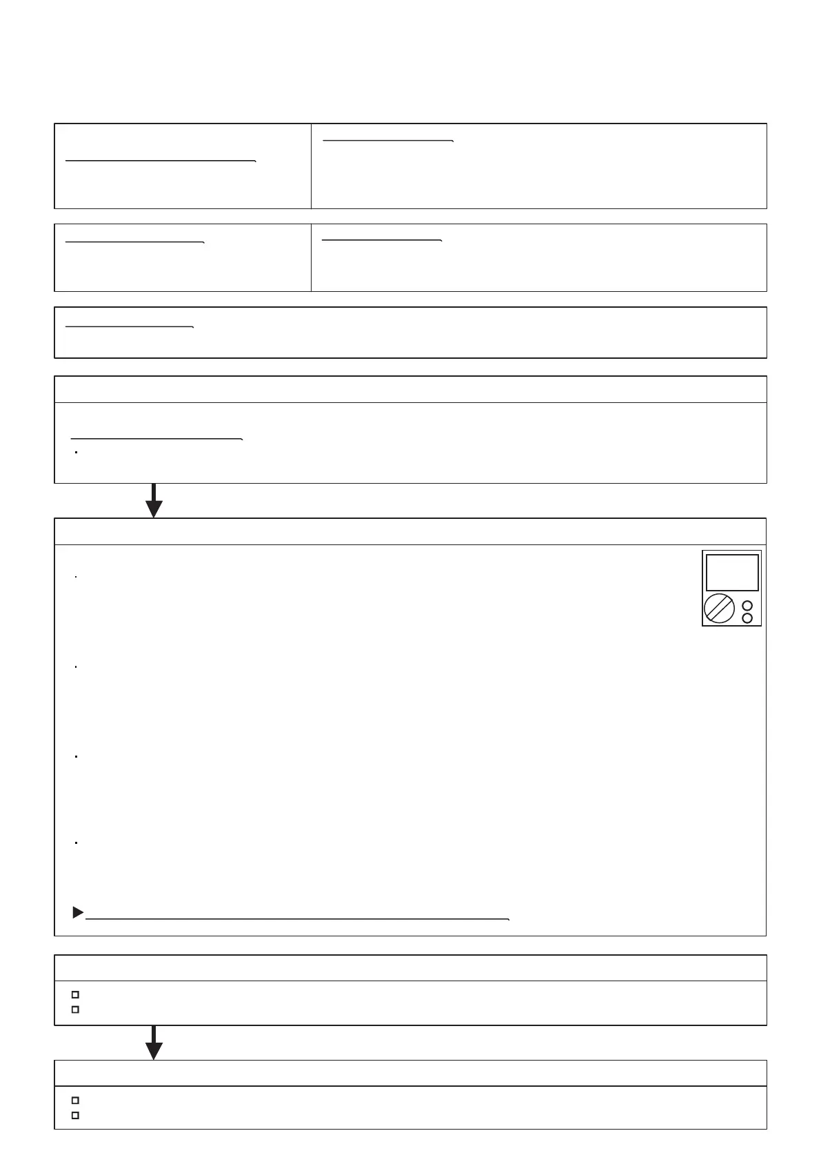
Check Voltage at CN300 of Controller PCB. (Terminal 1-3, Terminal 1-2)
(Power supply for the Remote Control)
Check Point 2 : Wire installation Wrong RCgroup setting
Wrong wire connection in RCgroup (Please refer to the installation manual)
The number of connecting indoor unit and Remote controller in one RCgroup were less than 16 units.
Check if controller PCB damage.
Change controller PCB and check the Error after setting remote controller address.
Check Point 2-1 : Check Indoor unit controller PCB
Check Voltage at CN300 (Terminal 1-2) of UTY-TWRXZ2 (Communication kit).
(Power supply to Remote control)
For AS* G __ KGTB
>> If it is DC12V, Remote control is failure. (Controller PCB is normal) >> Replace Remote control
>> If it is DC 0V, Controller PCB is failure. (Check Remote control once again) >> Replace Controller PCB
Check Voltage at CNC01 (Terminal 1-3) of UTY-TWBXF2 (Communication kit).
(Power supply to Remote control)
For AS* G __ KMTB
For AR type
For AU type
>> If it is DC13V, Remote control is failure. (Controller PCB is normal) >> Replace Remote control
>> If it is DC 0V, Controller PCB is failure. (Check Remote control once again) >> Replace Controller PCB
>> If it is DC13V, Remote control is failure. (Controller PCB is normal) >> Replace Remote control
>> If it is DC 0V, Controller PCB is failure. (Check Remote control once again) >> Replace Controller PCB
Check Voltage at CN14 of Controller PCB. (Terminal 1-3, Terminal 1-2)
(Power supply for the Remote Control)
Upon correcting the removed connector or mis-wiring, reset the power.
>> If it is DC12V, Remote control is failure. (Controller PCB is normal) >> Replace Remote control
>> If it is DC 0V, Controller PCB is failure. (Check Remote control once again) >> Replace Controller PCB
DC
 Loading...