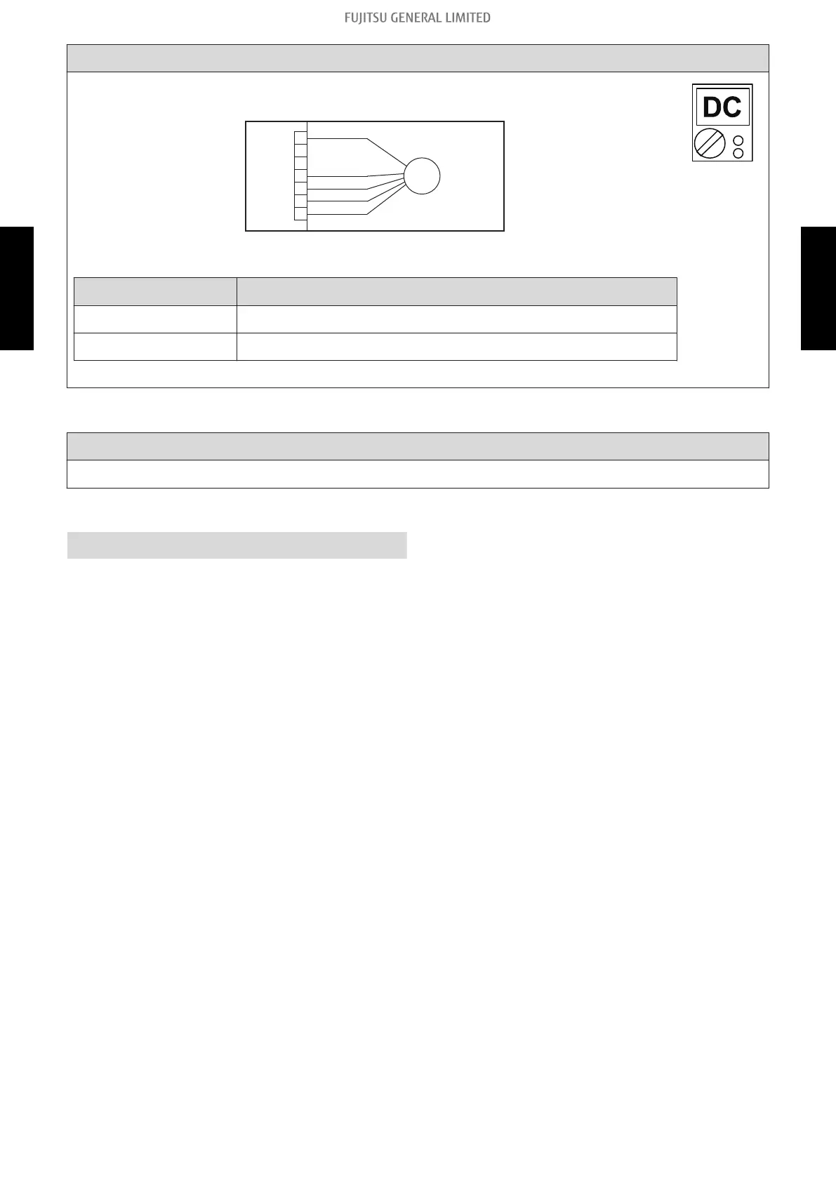
Check point 4. Check output voltage of inverter PCB
Check outdoor unit circuit diagram and the voltage. (Measure at inverter PCB side
connector)
1
2
3
4
5
6
7
BLACK
WHITE
YELLOW
RED
FM
FAN MOTOR
BROWN
NOTE:
For details of wiring diagram, refer to "Wiring diagrams" in Chapter 2.
TECHNICAL DATA AND PARTS LIST on page 02-37.
Read wire
DC voltage
Red—Black 280 V (AC 220 V -10%) to 373 V (AC 240 V +10%)
White—Black 15 ± 1.5 V
-> If the voltage is not correct, replace inverter PCB.
↓
Check point 5. Replace main PCB
If Check point 1 to 4 do not improve the symptom, change main PCB.
↓
End
2-31. E: 97. Outdoor unit fan motor error (Outdoor unit) - (03-39) - 2. Troubleshooting with error code
TROUBLESHOOTING
TROUBLESHOOTING
 Loading...