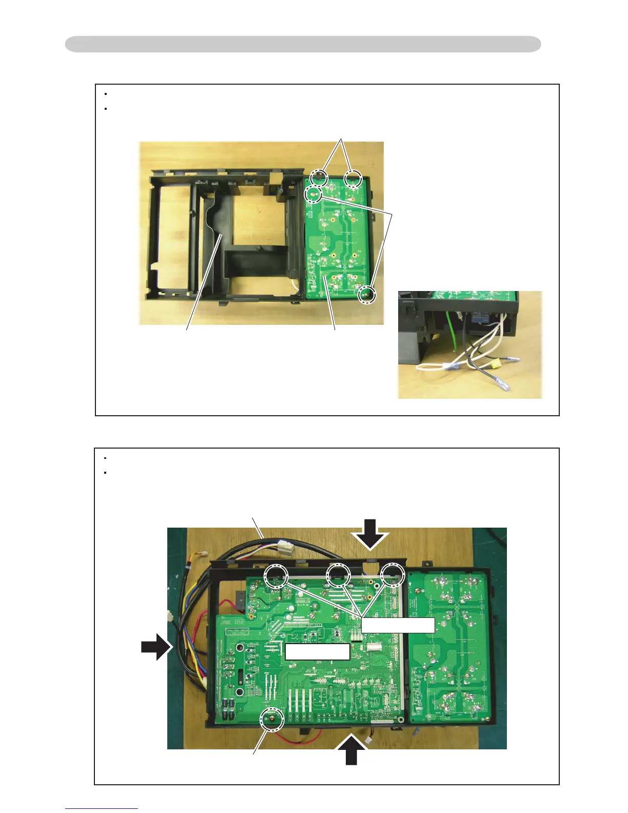
EasyManuals Logo

Fujitsu AS*12LMACW Service Instruction

Fujitsu AS*12LMACW
116 pages
To Next Page IconTo Next Page
To Previous Page IconTo Previous Page
Page #111 background imageLoading...
Page #111 background image
1. FILTER PCB
As shown in Fig.1, assemble FILTER PCB to INVERTER BOX A.
As shown in Fig.2, pull out the wires of FILTER PCB.
2. MAIN PCB
As shown in Fig.3, temporarily fix MAIN PCB to INVERTER BOX A.
After it is temporary fix of MAIN PCB, As shown in the Fig 4 - 7,
pull out the wires of MAIN PCB.
1-2-4 ASSEMBLY PROCESS of INVERTER UNIT (For AO*30LMAW4)
03-16
Screw (2 places)
Hook (2 places)
Fig.1
Fig.3
Fig.2
FILTER PCBINVERTER BOX A
W12(Yellow)
W13(Blue)
Screw
Fig.5
Fig.4
Fig.6/ 7
Hook (3 places)
MAIN PCB

Other manuals for Fujitsu AS*12LMACW

Questions and Answers:

Question and Answer IconNeed help?

Do you have a question about the Fujitsu AS*12LMACW and is the answer not in the manual?

Fujitsu AS*12LMACW Specifications

General IconGeneral
BrandFujitsu
ModelAS*12LMACW
CategoryAir Conditioner
LanguageEnglish

Related product manuals