– –
– 149 –
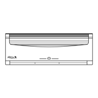
Do not install the unit so that the drain
hose side is too high. Height A should be
less than 5 mm (Fig. 11).
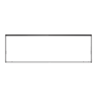
Be sure to arrange the drain hose so that it is leveled
lower than the drain hose connecting port of the
indoor unit.
Fig. 10
OK
NO
NO
Drain hose
Arrange the drain hose
lower than this portion
Fig. 11
Drain hose
A
A
BAD
BAD
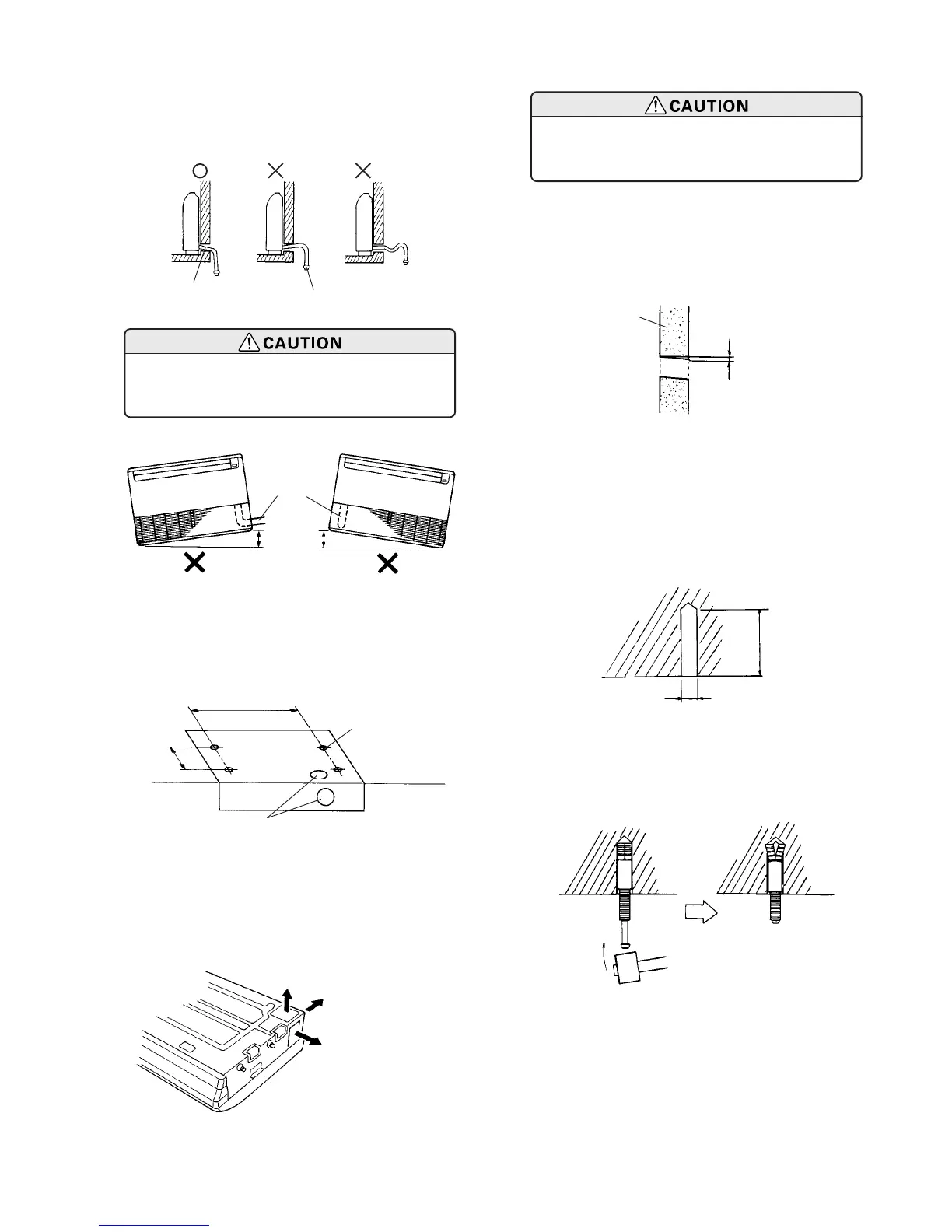
When the directions are selected, drill 3-1/8” (80 mm)
and 2” (50 mm) or 6” (150 mm) dia. hole on the wall
so that the hole is tilted downward toward the outdoor
for smooth water flow.
Fig.12
35.4" (900 mm)
7-7/8"
(200 mm)
Installation
template
Install the drain hose at the rear; it
should not be installed on the top or
right side.
B. UNDER CEILING TYPE
Using the installation template, drill holes for piping
and anchor bolts (for holes) (Fig. 12).
2. DRILLING HOLES FOR ANCHOR BOLTS AND
INSTALLING THE ANCHOR BOLTS
With a concrete drill, drill four 1/2” (12.7 mm) dia.
holes (Fig. 15).
Insert the anchor bolts into the drilled holes, and drive
the pins completely into the anchor bolts with a ham-
mer (Fig. 16).
1. DRILLING FOR PIPING
Select piping and drain directions (Fig. 13).
Drilling position
for anchor bolt
Ceiling
Wall
Drilling position
for piping
Fig.14
Wall
1/4" (6 mm)
Indoor side
Outdoor side
Fig.15
ø1/2" (12.7 mm)
2-3/8" to 2-3/4"
(60 to 70 mm)
Fig.16
Fig.13
Top
Rear
(Install the drain hose
in this direction.)
Right
 Loading...