3
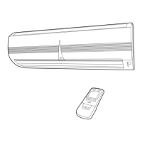
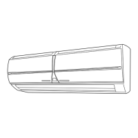
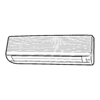
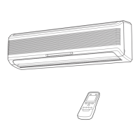
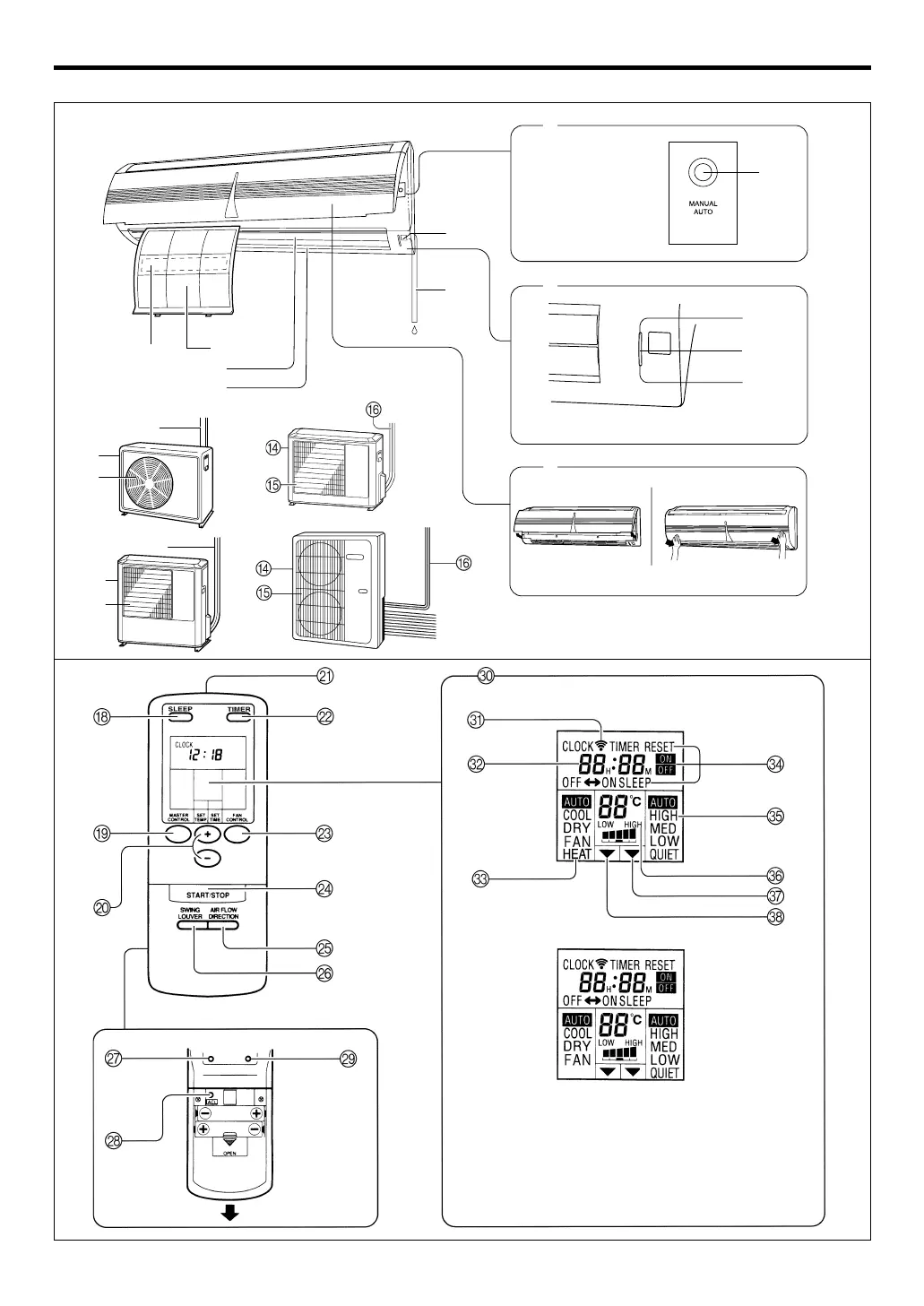
NAME OF PARTS
Fig. 5
Fig. 6
Fig. 1
Fig. 2
Fig. 3
Fig. 4
Fig. 8
To facilitate explanation, the accompanying illustra-
tion has been drawn to show all possible indicators;
in actual operation, however, the display will only
show those indicators appropriate to the current op-
eration.
Fig. 7
Instructions relating to heating (*) are applicable only to “HEAT & COOL MODEL” (Reverse Cycle).
* HEAT & COOL MODEL (REVERSE CYCLE)
COOLING MODEL
A
0
C
3
1
4
5
6
8
7
OPENATION
TIMER
SWING
B
9
2
F
D
E
F
D
E
9374666010_OM_en.p65 1/4/05, 3:27 PM3
 Loading...