EasyManuals Logo

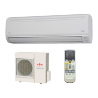
Fujitsu ASU18RMLQ User Manual

Fujitsu ASU18RMLQ
145 pages
To Next Page IconTo Next Page
To Previous Page IconTo Previous Page
Page #107 background imageLoading...
Page #107 background image
REPLACEMENT PARTS
03-27
Fig.4
CN1
(from CN1 of MAIN PCB)
WHITE
Fig.5
TM102
WIRE WITH TERMINAL
WHITE LINE
(from W11 of MAIN PCB)
TM101
WIRE WITH TERMINAL
BLACK LINE
(from W10 of MAIN PCB)
Through this hole.
REGULATIONS
MODEL : AOU24RML
As shown in Fig.4-5, connect wires. PWB must not warp when you connect CN1.

Other manuals for Fujitsu ASU18RMLQ

Questions and Answers:

Question and Answer IconNeed help?

Do you have a question about the Fujitsu ASU18RMLQ and is the answer not in the manual?

Fujitsu ASU18RMLQ Specifications

General IconGeneral
BrandFujitsu
ModelASU18RMLQ
CategoryAir Conditioner
LanguageEnglish

Related product manuals