REPLACEMENT PARTS
03-17
PROCESS
MODEL : AOU24RML
USED
PARTS
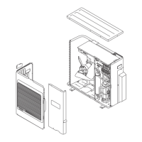
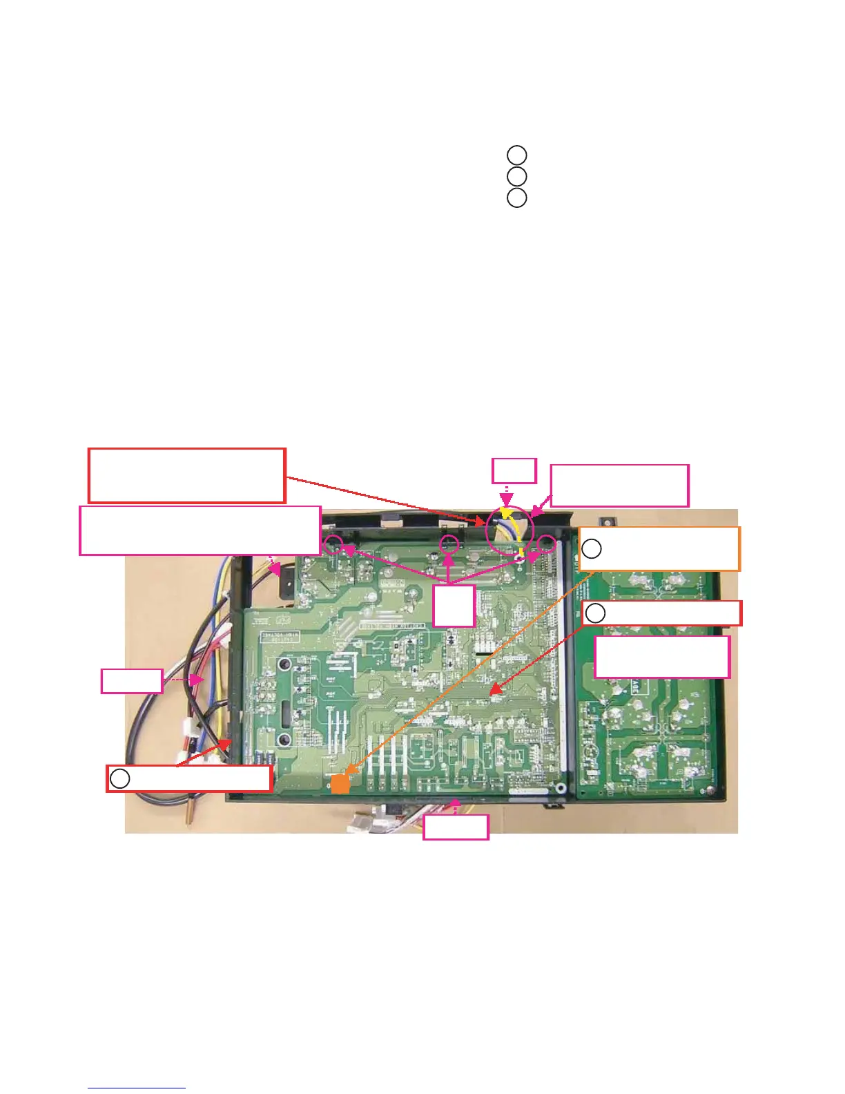
INVERTER BOX A
MAIN PCB
Fig.1
Hook
SCREW, TAPPING
Temporarily fix!
Through this hole.
W12 YELLOW,W13 BLUE
(MAIN PWB)
WIRE WITH TERMINAL
Fig.7
Fig.8-10
Fig.6
Don't forget to take a cushion.
Don't bend foot.
INVERTER BOX A
MAIN PCB
SCREW, TAPPING
Assemble PCB ASSY
(MAIN PWB)
REGULATIONS
Certainly set PWB ASSY under the 3 hooks of INVERTER BOX A.
Before it is temporary fix of PCB ASSY, As shown in the Fig.2-5, pull out the wires of PCB ASSY.
After it is temporary fix of PCB ASSY, As shown in the Fig.6-10, pull out the wires of PCB ASSY.
Don't forget to take a cushion D101(DIODE BRIDGE).
Don't bend foot D101(DIODE BRIDGE).
1
1
2
2
3
3
 Loading...