Do you have a question about the Fujitsu ASUG09LMAS and is the answer not in the manual?
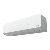
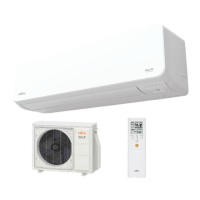
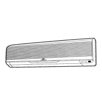
Detailed specifications for the indoor unit, covering capacity, power, dimensions, and performance.
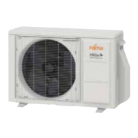
Detailed specifications for the outdoor unit, covering capacity, power, dimensions, and performance.
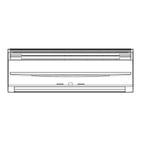
Diagrams and measurements for the indoor unit's physical size and mounting.
Diagrams and measurements for the outdoor unit's physical size and mounting.
Essential safety and handling precautions for servicing the unit.
Exploded views and part numbers for the indoor unit's components.
Exploded views and part numbers for the outdoor unit's components.
List of included accessories for the indoor and outdoor units.
List of optional components and their functions, such as remote controllers.
Visual representation of the refrigerant circuit and its components.
Electrical wiring schematics for the indoor unit.
Electrical wiring schematics for the outdoor unit.
Schematic diagrams of the printed circuit boards for the indoor unit.
Schematic diagrams of the printed circuit boards for the outdoor unit.
Table listing error codes, their causes, and indicator patterns.
Detailed steps to diagnose and resolve specific error codes.
Steps to diagnose and resolve the E:11 serial communication error for the outdoor unit.
Steps to diagnose and resolve the E:11 serial communication error for the indoor unit.
Steps to diagnose and resolve the E:12 communication error with the wired remote controller.
Steps to diagnose and resolve the E:18 external communication error.
Steps to diagnose and resolve the E:32 error related to the indoor unit's main PCB.
Steps to diagnose and resolve the E:35 error related to the MANUAL AUTO button.
Steps to diagnose and resolve the E:41 error for the room temperature sensor.
Steps to diagnose and resolve the E:42 error for the indoor heat exchanger sensor.
Steps to diagnose and resolve the E:51 error for the indoor unit fan motor.
Steps to diagnose and resolve the E:62 error for the outdoor unit's main PCB.
Steps to diagnose and resolve the E:64 PFC circuit error.
Steps to diagnose and resolve the E:71 error for the discharge thermistor.
Steps to diagnose and resolve the E:73 error for the outdoor heat exchanger thermistor.
Steps to diagnose and resolve the E:74 error for the outdoor temperature thermistor.
Steps to diagnose and resolve the E:84 error for the current sensor.
Steps to diagnose and resolve the E:94 trip detection error.
Steps to diagnose and resolve the E:95 compressor motor control error.
Steps to diagnose and resolve the E:97 outdoor unit fan motor error.
Steps to diagnose and resolve the E:99 4-way valve error.
Steps to diagnose and resolve the E:A1 discharge temperature error.
Steps to diagnose and resolve issues not indicated by error codes.
Steps to troubleshoot when the indoor unit has no power.
Steps to troubleshoot when the outdoor unit has no power.
Steps to troubleshoot when the unit is on but not operating.
Steps to troubleshoot when the unit is not cooling or heating.
Steps to diagnose and resolve abnormal noises coming from the unit.
Steps to diagnose and resolve issues related to water leaking from the unit.
Information and troubleshooting guides for key service parts.
Troubleshooting and information related to the compressor.
Specific troubleshooting and information for the inverter compressor.
Troubleshooting and information for the outdoor unit's Electronic Expansion Valve.
Troubleshooting and information for the indoor unit's fan motor.
Troubleshooting and information for the outdoor unit's fan motor.
Resistance and voltage values for indoor unit thermistors at various temperatures.
Resistance and voltage values for outdoor unit thermistors at various temperatures.
How compressor frequency is managed based on operating conditions.
How compressor frequency is controlled during cooling operation based on temperature.
How compressor frequency is controlled during heating operation based on temperature.
How compressor frequency is controlled during dry operation.
The sequence of compressor frequency adjustment upon starting the unit.
How outdoor temperature limits the compressor frequency.
How the unit automatically switches between cooling, heating, and dry modes.
Controls for fan speed and airflow direction.
Controls for indoor fan speed and airflow direction in different modes.
Fan speed control for the outdoor unit based on temperature and frequency.
Controls for louvers and airflow direction.
How to control the vertical louver position and swing operation.
How to adjust the horizontal louvers for desired airflow direction.
Details on vertical airflow swing operation for cooling and heating modes.
Settings for various timer operations.
Settings for On/Off, Program, Sleep, and Weekly timers using the wireless remote.
Timer functions available with the wired remote control.
Conditions and procedures for defrost operation in heating mode.
How defrost operates when heating is stopped due to frosting.
Details on various operational controls and functions.
Functionality of the auto-restart feature after power interruption.
How to operate the unit manually without a remote controller.
How to initiate a forced cooling operation mode.
Specifics of the 10°C heating operation mode.
Details on the economy operation mode for energy saving.
Details on the powerful operation mode for maximum output.
The process of preheating the compressor for faster warm airflow.
Control mechanism for the electronic expansion valve.
Mechanism preventing compressor restarts within a 3-minute interval.
How the 4-way valve operates during mode changes and heating.
Functionality of the outdoor unit's low noise operation mode.
Protective controls to ensure safe and reliable operation.
Control logic for preventing high discharge gas temperatures.
Control logic to prevent freezing in cooling and dry modes.
Control to limit compressor frequency based on outdoor unit current.
Protection mechanism against high cooling pressure.
Protection mechanism for operation at low outdoor temperatures.
Control logic for high temperature and pressure conditions.
Adjusting unit functions to suit the installation environment.
Procedures for accessing and modifying unit functions via the remote controller.
How to set the custom code for wireless remote controller pairing.
Overview of external input/output PCB and its connections.
Details on using external inputs for controlling unit operation.
Details on using external outputs for monitoring unit status.
Various combinations of external inputs and outputs with rotary switch settings.
Specific input signal types and commands for control functions.
| Brand | Fujitsu |
|---|---|
| Model | ASUG09LMAS |
| Category | Air Conditioner |
| Language | English |