EasyManua.ls Logo

Fujitsu ASY17USCQ - User Manual

Fujitsu ASY17USCQ
19 pages
To Next Page IconTo Next Page
Loading...
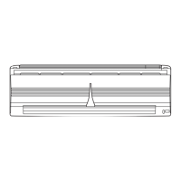
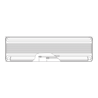
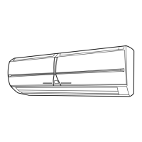
SPLIT TYPE ROOM AIR
CONDITIONER
WALL MOUNTED
type
CONTENTS
SPECIFICATIONS
. . . . . . . . . . . . . . . . .
1
REFRIGERANT SYSTEM DIAGRAM
. . .
3
CIRCUIT DIAGRAM
. . . . . . . . . . . . . . . .
4
PCB CIRCUIT DIAGRAM
. . . . . . . . . . . .
6
OUTLINE AND DIMENSIONS
. . . . . . . .
2
DISASSEMBLY ILLUSTRATION
. . . . . . .
9
FAILURE DETECTION
. . . . . . . . . . . . . .
8
PARTS LIST
. . . . . . . . . . . . . . . . . . . . .
15
Indoor unit Outdoor unit
ASY17FSBQ AOY17FNBK
ASY17USBQ AOY17UNBK
( made in Thailand )
ASY17FSCQ AOY17FNBN
ASY17USCQ AOY17UNBN
( made in China )
Question and Answer IconNeed help?

Do you have a question about the Fujitsu ASY17USCQ and is the answer not in the manual?

Fujitsu ASY17USCQ Specifications

General IconGeneral
RefrigerantR410A
TypeSplit System
Cooling Capacity17000 BTU/h
HSPF Rating9.0 HSPF
Voltage208/230V

Summary

Specifications

Electrical Data

Electrical specifications including power source, current, and input watts.

Refrigerant Charge (R410 A)

Refrigerant charge amounts based on pipe length for R410A.

Refrigerant System Diagram

Model ASY17 FSBQ;AOY17 FNBK Diagram

Refrigerant flow diagram for specific indoor and outdoor unit models.

Circuit Diagram

PCB Circuit Diagram

Indoor Unit PCB Diagram

Detailed circuit diagram for the indoor unit's main printed circuit board.

Failure Detection

Room Thermistor Failure

Identifies room thermistor failure by operation lamp flash count.

Heat Exchanger Thermistor Failure

Identifies heat exchanger thermistor failure by timer lamp flash count.

Related product manuals