Do you have a question about the Fujitsu ASY18LMA-W and is the answer not in the manual?
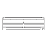
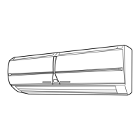
Details electrical data, fan motor, noise levels, and measurements for the indoor unit.
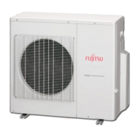
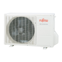
Covers electrical data, fan motor, compressor, and measurement details for the outdoor unit.
Provides detailed drawings and measurements for the indoor unit.
Presents diagrams and measurements for the outdoor unit.
Illustrates the refrigerant flow and components in the system.
Shows the electrical wiring and components for the indoor unit.
Details the electrical connections and components for the outdoor unit.
Detailed schematic of the indoor unit's printed circuit board.
Detailed schematic of the outdoor unit's printed circuit board.
Diagram of the outdoor unit's power supply PCB assembly.
Explains how OPERATION, TIMER, and SWING lamps indicate specific errors.
Lists error codes indicated by LEDs on the outdoor unit.
Illustrates and lists parts for the indoor unit's front panel assembly.
Details parts related to the indoor unit's evaporator assembly.
Lists various internal parts of the indoor unit, such as fan motor and bearings.
Shows components for the indoor unit's drain pan and hose.
Details parts for the indoor unit's louver assembly.
Illustrates the sub-assembly for the indoor unit's louver link mechanism.
Shows parts for the indoor unit's motor base sub-assembly.
Lists components for the indoor unit's control unit.
Lists accessories for mounting, remote operation, and power for the indoor unit.
Details tapping screws and air cleaning filters for the indoor unit.
Details external parts of the outdoor unit, like panels and guards.
Lists internal parts such as fan motor, condenser, and base assembly.
Details parts of the outdoor unit's refrigerant circuit, including valves and pipes.
Lists components specific to the outdoor unit's compressor assembly.
Details parts of the outdoor unit's inverter assembly, including PCBs and heat sinks.
| Brand | Fujitsu |
|---|---|
| Model | ASY18LMA-W |
| Category | Air Conditioner |
| Language | English |