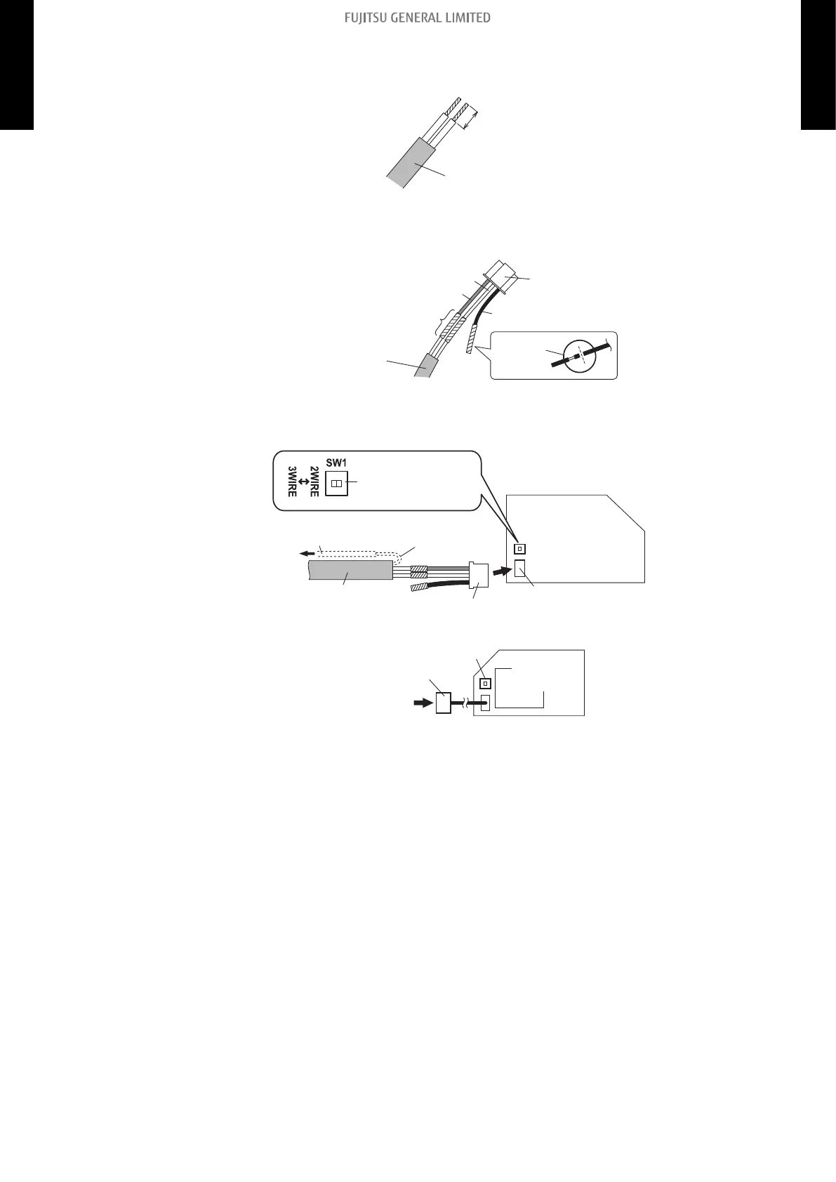
• Pattern B
1. Use a tool to cut off the terminal on the end of the remote controller cable, and then remove
the insulation from the cut end of the cable as shown below.
Remote
controller cable
(Non-polar)
20 mm
2. Connect the remote controller cable and connecting cable as shown below. Be sure to insu-
late the connection between the cables.
Remote
controller cable
(Non-polar)
Insulated
connection
White
Black
Red
Connecting
cable
Cut and
insulate
3. Connect the remote controller cable to the connecting cable, and insert it to the connector.
Set the DIP switch (SW1) to “2WIRE” on the PCB of the indoor unit.
Indoor unit
PCB
Remote controller
cable (Non-polar)
Connecting cable
Connector CNC01
(onboard)
Connect to earth
(ground) screw
Functional grounding
(If necessary)
Set the DIP switch
(SW1) to “2WIRE”
NOTE: Layout of terminal block and PCB is varies depending on the type of indoor unit.
Connector
(adapter)
SW1
Indoor unit
PCB
- 289 -
14-11. Wired remote controller (UTY-RCRYZ1: Optional part)
14. Remote controller
4-5 UNIT
MULTI-SPLIT TYPE
4-5 UNIT
MULTI-SPLIT TYPE
 Loading...