5. CONTROL SYSTEM
FUNCTIONS
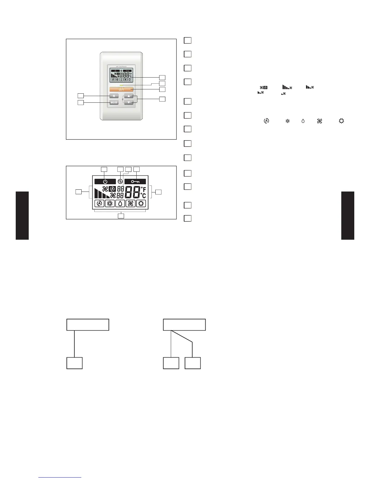
Display panel
6
5
4
1
2
3
7
8
9
10
11
12
13
*1: during Error code history display mode.
*2: during address display mode.
*3: during self Diagnosis mode.
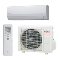
SYSTEM DIAGRAM
1 remote controller
2 remote controllers
A , B , C : Remote controller cable.
A
<
=
500m ; B+C
<
=
500m
Indoor unit
Remote controller
A
Remote controllers
Primary
Secondary
Indoor unit
BC
Note: Some button operations may not be available for all units
or systems. For details, please see operation manual.
Start/Stop button1
Pressed to start and stop operation.
Display background light2
Lights during operation.
Operation lamp3
Lights during operation.
Fan button4
Selects the fan speed (AUTO , HIGH , MED ,
LOW
,
QUIET ).
Set temp. button5
Selects the setting temperature.
Mode button6
Selects operating mode (AUTO , COOL , DRY ,FAN , HEAT
).
Standby indicator7
Indicates oil recovery and defrosting operation.
Power source indicator8
Indicates the main power ON.
Central control indicator9
Indicates when function is locked.
Fan speed indicator10
Set temperature indicator11
Indicates error history number. *1
Indicates Indoor unit address. *2
Operating mode indicator12
(Upper) Indicates the error code *1 *313 / the refrigerant
system address. *2
(Lower) Indicates the remote controller address. *1 *2 *3
- (05 - 32) -
CONTROL
SYSTEM
CONTROL
SYSTEM