5. CONTROL SYSTEM
INSTALLATION
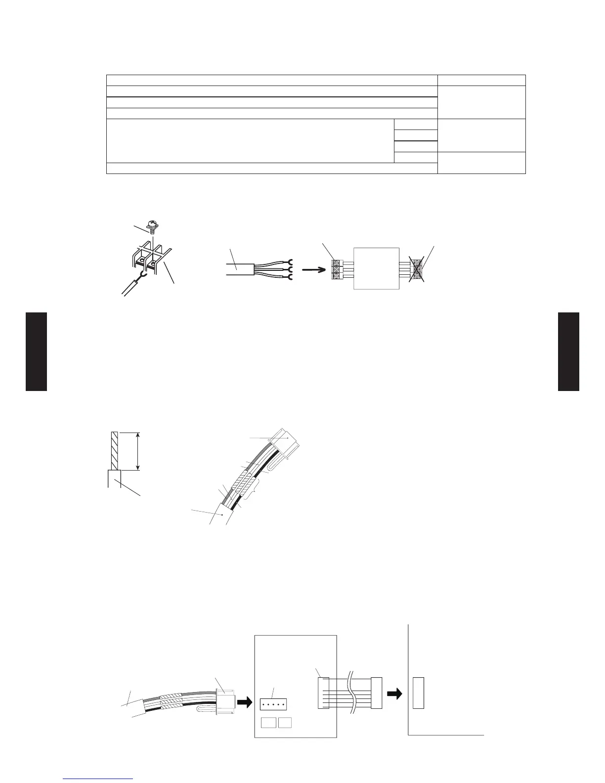
Connection Pattern
Note: Connection pattern is different according to type of Indoor unit.
Indoor unit types Connection Pattern
Compact Cassette type
Pattern ASlim Duct type
Floor / Ceiling type
Wall Mounted type
LJ
Pattern BLU
LM
LF
Pattern C
Floor type
Pattern A
Connect the end of remote controller cable directly to the exclusive terminal block.
PCB
M4 screw
Terminal block
Remote
controller
cable
Remote controller
terminal block
Indoor unit
Outdoor unit /
Power supply
terminal block
Note: It may fail to work if it is connected to the outdoor unit or the terminal block for power
supply.
Pattern B
1) Modify the remote controller cable as per below methods.
Use a tool to cut off the terminal on the end of the remote controller cable and then remove
the insulation from the cut end of the cable as shown in Fig.
Connect the remote controller cable and connecting cable as shown in Fig.
Be sure to insulate the connection between the cables.
20 mm
Remote controller
cable
Connecting
cable
Insulated
connection
Red
Red
White
White
Black
Black
2) Method of connecting remote controller cable
Connecting cable made by above-mentioned 1) is connected with Terminal A of optional
communication kit .
Cable connected with Terminal B of communication kit is connected with PCB of Indoor unit.
A: (CN305) -(LJ type: UTY-XCBX Z1) B: (CN301) -(LJ type: UTY-XCBX Z1)
(CNC01)-(LU type: UTY-TWBXF) (CND01) -(LU type: UT Y-T WBXF)
(CNC01)-(LM type: UTY-XCBXZ2) (CND01)-(LM type: UT Y-XCBX Z2)
Remote controller
cable
Connecting
cable
Communication kit Indoor unit PCB
Terminal B
Terminal A
- (05 - 34) -
CONTROL
SYSTEM
CONTROL
SYSTEM
 Loading...