2. MODEL SELECTION
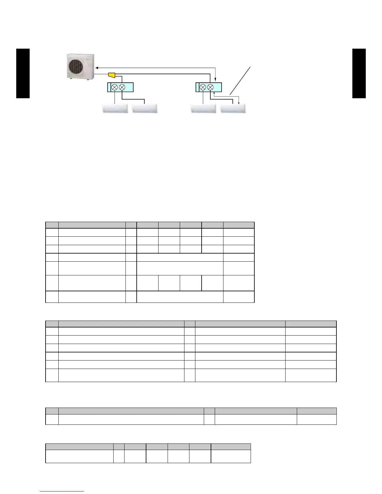
EXAMPLE 2
(When the connecting capacity for indoor unit is 100% or less)
Branch
box
Branch
box
Outdoor unit
Indoor unit 1 Indoor unit 2 Indoor unit 3 Indoor unit 4
Room 1 Room 2 Room 3 Room 4
Main Piping length, L1=10m Branch Piping length, L2=10m
Design conditions
Design temperature
Indoor : 23.0°C DB / 16.0°C WB
Outdoor : 30.0°C DB
Pipe length
Main piping length : L1=10m
Branch piping length : L2=10m
Operation mode: Cooling
Selection of indoor unit
Room 1 Room 2 Room 3 Room 4
Remark
A-1 Cooling heat load kW 2.2 2.2 2.9 2.9
A-2 Indoor unit models
AS09 AS09 AS12 AS12
A-3 Rated capacity (TC
in
)
r
kW 2.64 2.64 3.52 3.52
Cooling
A-4 i (
in
)
r
2.64 x 2 + 3.52 x 2 = 12.3
Sum of A-3
A-5
Connecting indoor unit
capacity (Cp)
12. / 1. 7. (1)
A-6
Capacity at design temperature
(TC
in
)
d
kW 2.30 2.30 3.06 3.06
See 6-1.
A-7
Total capacity at design
m (
in
)
d
kW 2.30 x 2 +3.06 x 2 = 10.7
Sum of A-6
Calculate the Maximum capacity of outdoor unit
Remark
B-1 Outdoor unit model AO
G45LBT8
B-2 Rated capacity (TC
out
)
r
kW 14.0
Cooling
B-3 Capacity change rate by temperature conditions 13.9 / 14.0 = 0.993
Se e Fi g.1
B-4 Capacity change rate by indoor units connecting capacity kW 14.0 *1
B-5 mnin in i n 0.98 x 0.942 = 0.923
See 5-1.
B-6 Maximum capacity of outdoor unit (TC
out
)
c
kW 14.0 x 0.993 x 0.923 = 12.8
(B-4) x (B-3) x (B-5)
*1: When indoor units connecting capacity is 100% or less, rated capacity is used.
Decide system capacity
Remark
C-1 System capacity kW 10.7
Smaller one of (A-7)
and (B-6)
Calculate actual capacity of each indoor unit
Room 1 Room 2 Room 3 Room 4
Remark
Actual capacity of each indoor
unit
kW 2.30 2.30 3.06 3.06
(A3) x (C1) / (A4)
Actual capacity of all indoor units is larger than cooling heat load of each room.
- (02 - 06) -
MODEL
SELECTION
MODEL
SELECTION