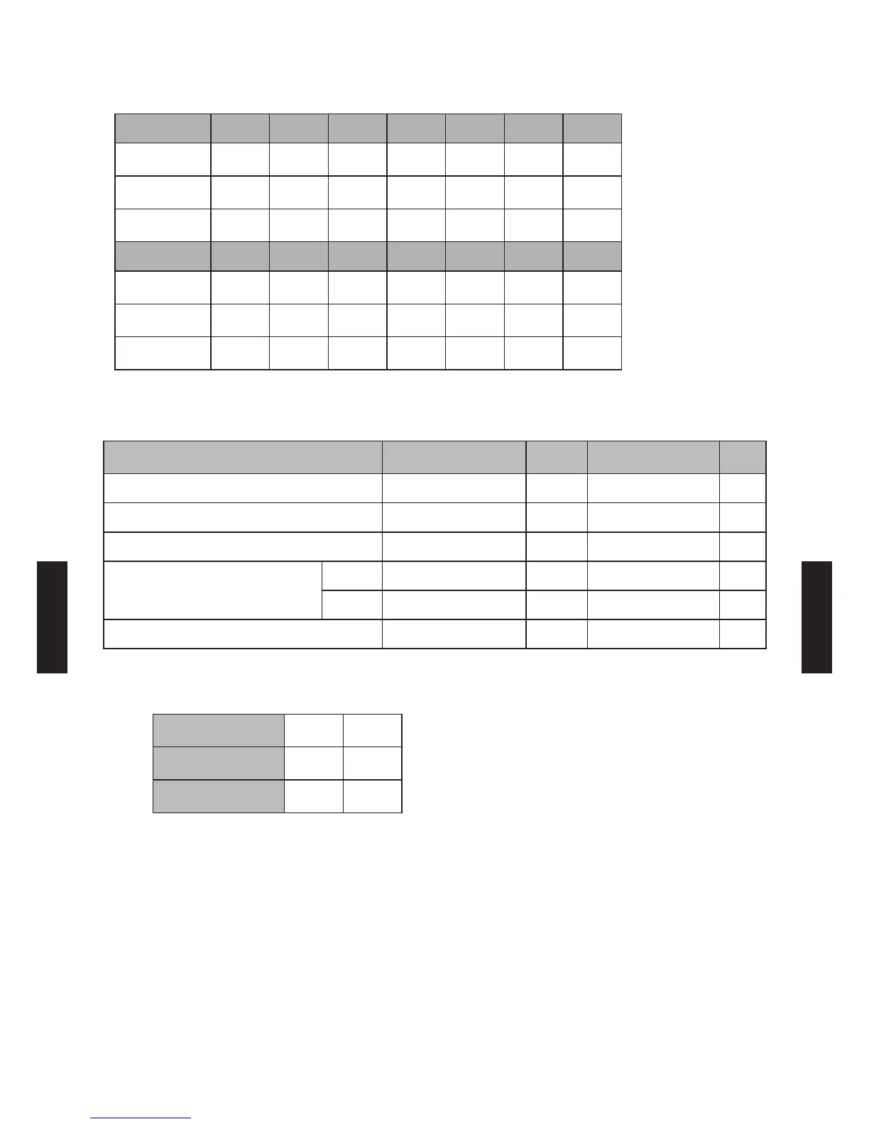
6. SYSTEM DESIGN
Selection of pipe size
a b c d e f g
Liquid pipe size
mm (in.)
9.52
(3/8)
9.52
(3/8)
9.52
(3/8)
9.52
(3/8)
9.52
(3/8)
6.35
(1/4)
6.35
(1/4)
Gas pipe size
mm (in.)
15.88
(5/8)
15.88
(5/8)
15.88
(5/8)
15.88
(5/8)
15.88
(5/8)
9.52
(3/8)
9.52
(3/8)
Pipe length
m
7 10 10 5 5 5 5
h i j k l m
Liquid pipe size
mm (in.)
6.35
(1/4)
6.35
(1/4)
6.35
(1/4)
6.35
(1/4)
6.35
(1/4)
6.35
(1/4)
Gas pipe size
mm (in.)
9.52
(3/8)
9.52
(3/8)
9.52
(3/8)
9.52
(3/8)
9.52
(3/8)
9.52
(3/8)
Pipe length
m
5 5 5 5 5 8
Limitation check
Diagram
Example
m
Limitation
m
Judge
Total pipe length Total 80 115 or less
OK
Between outdoor unit and the farthest indoor unit a + b + c + m 35 70 or less
OK
Between outdoor unit and branch boxes a + b + c + d + e 37 55 or less
OK
Between branch box and indoor unit
Tot al f + g + h + i + j + k + l + m 43 60 or less
OK
Each unit f, g, h, i, j, k, l, m 5 to 8 Between 3 to 15
OK
etween outdoor unit and the rst separation tube a 7 5 or more
OK
Calculation of additional charge refrigerant
Liquid pipe size
mm (in.)
6.35
(1/4)
9.52
(3/8)
Additional refrigerant
g/m
21 58
Liquid pipe length
m
43 37
Additional charge = (21 x 43) + (58 x 37) = 3049 g = 3.05 kg
- (06 - 20) -
SYSTEM
DESIGN
SYSTEM
DESIGN
 Loading...