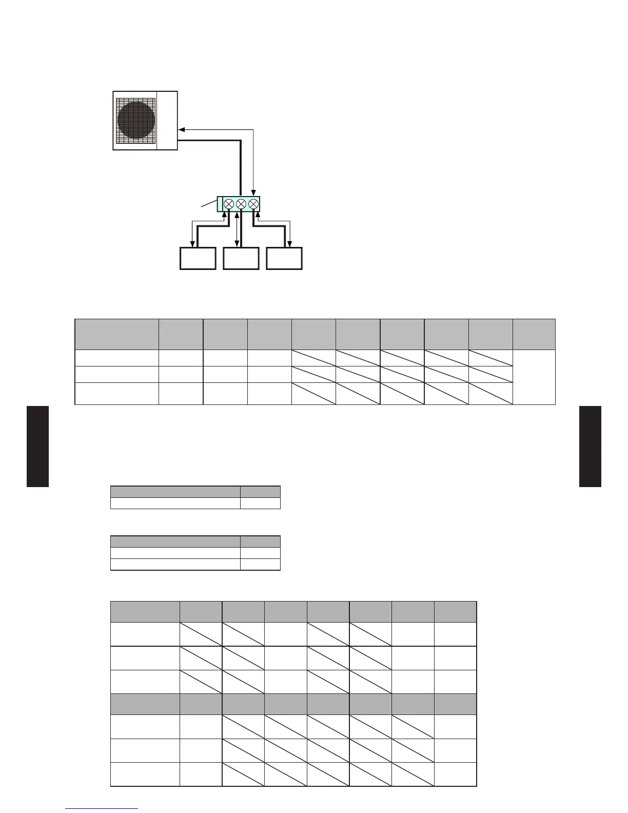
6. SYSTEM DESIGN
EXAMPLE 3
21 3
f g h
c
Outdoor unit
Branch box
Indoor unit Indoor unit Indoor unit
(7.0 kW) (5.0kW) (2.0kW)
System conguration
(Indoor units)
1 2 3 4 5 6 7 8
Total
capacity
(kW)
Model name AS24 AS18 AS07
14.35
Capacity class (kW) 7.0 5.0 2.0
Rated capacity of
cooling (kW)
7.03 5.27 2.05
Capacity ratio
(Total capacity of indoor units) / (Capacity of outdoor unit)
= (14.35) / (14.0) = 102.5% (Within 80% to 130%)
Selection of separation tube
Model Q'ty
UTP-SX248A None
Selection of branch box
Model Q'ty
UTP-PY03A (3 branches) 1
UTP-PY02A (2 branches) None
Selection of pipe size
a b c d e f g
Liquid pipe size
mm (in.)
9.52
(3/8)
6.35
(1/4)
6.35
(1/4)
Gas pipe size
mm (in.)
15.88
(5/8)
15.88
(5/8)
12.70
(1/2)
Pipe length
m
45 12 12
h i j k l m
Liquid pipe size
mm (in.)
6.35
(1/4)
Gas pipe size
mm (in.)
9.52
(3/8)
Pipe length
m
15
- (06 - 23) -
SYSTEM
DESIGN
SYSTEM
DESIGN
 Loading...