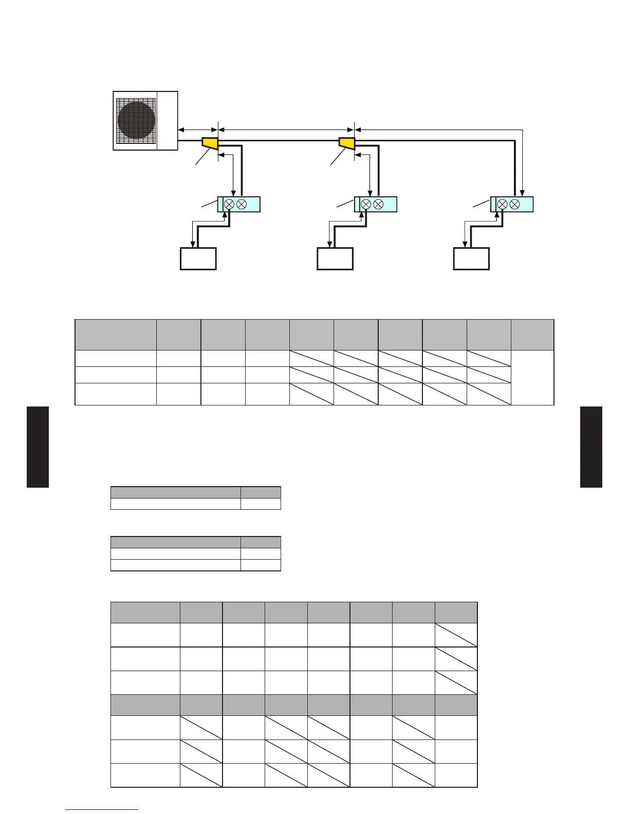
6. SYSTEM DESIGN
EXAMPLE 4
1 2 3
a b
d
f i l
e
c
Outdoor unit
Separation
tube
Branch box Branch box Branch box
Separation
tube
Indoor unit Indoor unit Indoor unit
(5.0kW) (5.0kW) (7.0 kW)
System conguration
(Indoor units)
1 2 3 4 5 6 7 8
Total
capacity
(kW)
Model name AS18 AS18 AS24
17.57
Capacity class (kW) 5.0kW 5.0kW 7.0 kW
Rated capacity of
cooling (kW)
5.27 5.27 7.03
Capacity ratio
(Total capacity of indoor units) / (Capacity of outdoor unit)
= (17.57) / (14.0) = 125.5% (Within 80% to 130%)
Selection of separation tube
Model Q'ty
UTP-SX248A 2
Selection of branch box
Model Q'ty
UTP-PY03A (3 branches) None
UTP-PY02A (2 branches) 3
Selection of pipe size
a b c d e f g
Liquid pipe size
mm (in.)
9.52
(3/8)
9.52
(3/8)
9.52
(3/8)
9.52
(3/8)
9.52
(3/8)
6.35
(1/4)
Gas pipe size
mm (in.)
15.88
(5/8)
15.88
(5/8)
15.88
(5/8)
15.88
(5/8)
15.88
(5/8)
12.70
(1/2)
Pipe length
m
7 18 18 5 5 12
h i j k l m
Liquid pipe size
mm (in.)
6.35
(1/4)
6.35
(1/4)
Gas pipe size
mm (in.)
12.70
(1/2)
15.88
(5/8)
Pipe length
m
12 12
- (06 - 25) -
SYSTEM
DESIGN
SYSTEM
DESIGN
 Loading...