6. SYSTEM DESIGN
Fix the unit (For wall installation)
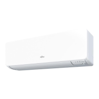
<Horizontal installation>
(1) Secure the hangers (accessories) with the
screws (2 pieces, Ø 4 x 10mm, accessories).
(4 places)
nsta the unit with its top side acing
upwards.
Screw
Hanger
Top side
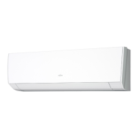
(2) For temporary mounting of the unit, install two
of the Ø 4×25mm screws in the wall, allowing
the space of 5 to 10mm between the wall and
the screw heads. Then hook the unit over
these two screws.
5 to 10 mm
469 mm
Pitch for securing
the tapping screws
Space
between wall
and head of
screw:
Tapping
screws
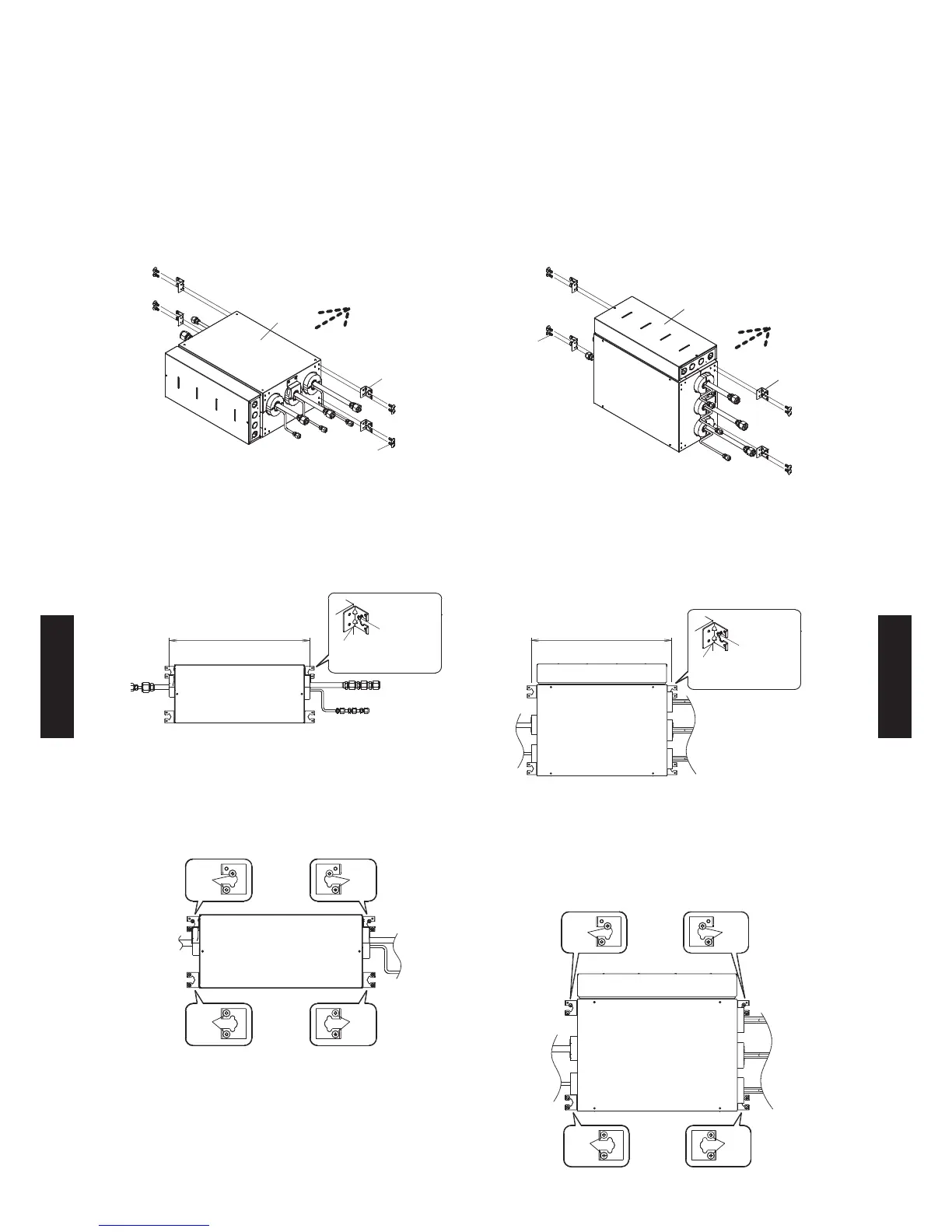
ter checing that the unit is at secure and
mount the branch box with the 8 screws (Ø
4 x 25mm, accessories) provided including
the tapping screws. (The unit’s slope must be
within ±5° in all directions.)
Screw
Screw
Screw
Screw
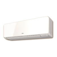
<Vertical installation>
(1) Secure the hangers (accessories) with the
screws (2 pieces, Ø 4 x 10mm, accessories).
(4 places)
nsta the unit with the contro bo acing
upwards.
Screw
Hanger
Control box
(2) For temporary mounting of the unit, install two
of the Ø 4×25mm screws in the wall, allowing
the space of 5 to 10mm between the wall and
the screw heads. Then hook the unit over
these two screws.
469 mm
5 to 10 mm
Pitch for securing
the tapping screws
Tapping
screws
Space
between wall
and head of
screw:
ter checing that the unit is at secure and
mount the branch box with the 8 screws (Ø
4 x 25mm, accessories) provided including
the tapping screws. (The unit’s slope must be
within ±5° in all directions.)
Screw
Screw
Screw
Screw
- (06 - 35) -
SYSTEM
DESIGN
SYSTEM
DESIGN
 Loading...