6. SYSTEM DESIGN
EXAMPLE4
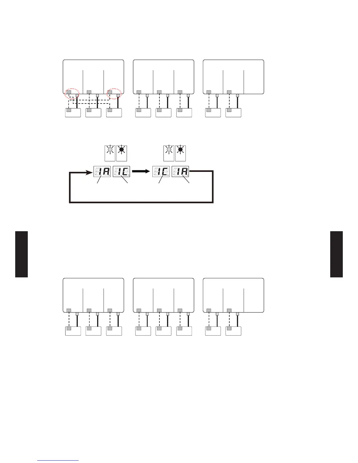
When connection destination does not match.
INDOOR UNIT A INDOOR UNIT B INDOOR UNIT C INDOOR UNIT A INDOOR UNIT B INDOOR UNIT C INDOOR UNIT A INDOOR UNIT B
Indoor
unit 1
Indoor
unit 2
Indoor
unit 3
Indoor
unit 4
Indoor
unit 5
Indoor
unit 6
Indoor
unit 7
Indoor
unit 8
Branch box 1 (Primary) Branch box 2 (Secondary) Branch box 3 (Secondary)
[Display (Check run ends)]
LED961 LED962
LED981
POWER
MODE
LED982
ERROR
LED961 LED962
LED981
POWER
MODE
LED982
ERROR
Switching every 2 seconds
Switching
every 2
seconds
Branch box 1
Indoor unit A
Branch box 1
Indoor unit C
Branch box 1
Indoor unit C
Branch box 1
Indoor unit A
to to
[Coping process]
1) The wire connected to Terminal Indoor unit A of Branch box1(Primary) must be rewired to
Terminal Indoor unit C of Branch box 1(Primary).
2) The wire connected to Terminal Indoor unit C of Branch box1(Primary) must be rewired to
Terminal Indoor unit A of Branch box 1(Primary).
[After correcting wiring]
INDOOR UNIT A INDOOR UNIT B INDOOR UNIT C INDOOR UNIT A INDOOR UNIT B INDOOR UNIT C INDOOR UNIT A INDOOR UNIT B
Indoor
unit 1
Indoor
unit 2
Indoor
unit 3
Indoor
unit 4
Indoor
unit 5
Indoor
unit 6
Indoor
unit 7
Indoor
unit 8
Branch box 1 (Primary) Branch box 2 (Secondary) Branch box 3 (Secondary)
- (06 - 101) -
SYSTEM
DESIGN
SYSTEM
DESIGN
 Loading...