6. SYSTEM DESIGN
EXTERNAL OUTPUT7-2-2.
OPERATION STATUS OUTPUT
Compact
Cassette
Slim Duct
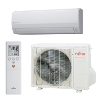
Wall Mounted
Floor /
Ceiling
Floor
LJ LU / LM LF
Connector CN103 CN103 CN304 CNB01 CN16 CN103 CN20
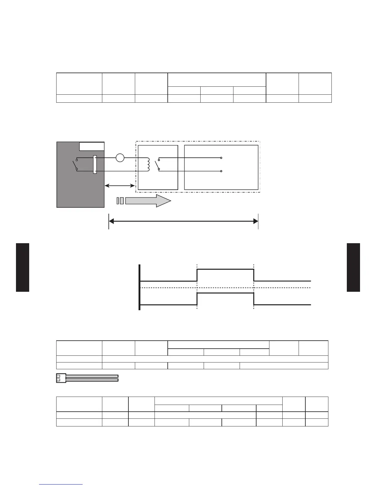
An air conditioner operation status signal can be output.
Circuit diagram example
*1 PC board of Communication kit is used for Wall mounted type..
*2 Make the distance from the PC board to the connected unit within 10 m.
Relay spec.: Max. DC 24 V, 10 mA to less than 500 mA.
ON
Parts (Optional)
Compact
Cassette
Slim Duct
Wall Mounted
Floor /
Ceiling
Floor
LJ LU / LM LF
Parts name External connect kit
Model name UT Y-XWZX UTD-ECS5A UT Y-X WZX UTY-XWZXZ5 UTY-XWZ X
Compact
Cassette
Slim Duct
Wall Mounted
Floor /
Ceiling
Floor
LJ LU LM LF
Parts name - - Communication kit - - -
Model name - - UT Y-XCBXZ1 UTY-TWBXF UT Y-XCBXZ2 - - -
*For operating the EXTERNAL OUTPUT function, the Wall mounted type (LJ, LU, LM) requires the communication kit
(UTY-XCBXZ1, UTY-TWBXF, UTY-XCBXZ2) in addition to the wire (UTY-XWZX, UTY-XWZXZ5).
 Loading...