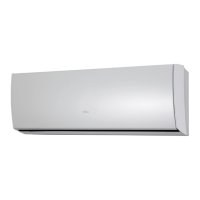
Do you have a question about the Fujitsu ASYG09LTCA and is the answer not in the manual?
| Cooling Capacity | 2.5 kW |
|---|---|
| Heating Capacity | 3.2 kW |
| Power Supply | 220-240V, 50Hz |
| Type | Split System |
| Refrigerant | R32 |
| Outdoor Unit Dimensions (WxHxD) | 240 mm |
Details electrical data including power source, frequency, current, voltage, EER, and COP.
Sound pressure levels for indoor and outdoor units at various operational speeds and modes.
Information on compressor type, refrigerant type, pre-charged refrigerant quantity, and pipe length.
Revolutions per minute (RPM) for the indoor unit's fan motor during cooling and heating cycles.
Physical dimensions (Height, Width, Depth) for both the indoor and outdoor units.
Shipping and net weight values for the indoor and outdoor units.
Detailed wiring diagram for the indoor unit's main controller PCB and its connections.
Schematic detailing the indoor unit's indicator PCB, components, and connectivity.
Detailed wiring diagram for the outdoor unit's controller PCB and its associated components.
Table listing indoor unit and wired remote error codes with corresponding explanations.
Guide to interpreting error conditions based on LED blinking patterns on the outdoor unit.
Breakdown and part numbers for the indoor unit's front panel, grille, and display components.
Breakdown and part numbers for the indoor unit's evaporator, pipes, and seals.
Breakdown and part numbers for the indoor unit's control box, motors, and terminal parts.
Breakdown and part numbers for the indoor unit's casing, covers, fan, and drain components.
Breakdown and part numbers for outdoor unit components like condenser, compressor, valves, and muffler.
Breakdown and part numbers for the outdoor unit's case, inverter, controller PCB, and terminals.
 Loading...