En-7
11.3.
Installing communication box
11.3.1. Removing intake grille
( Refer to “9.1. Front panel removal” )
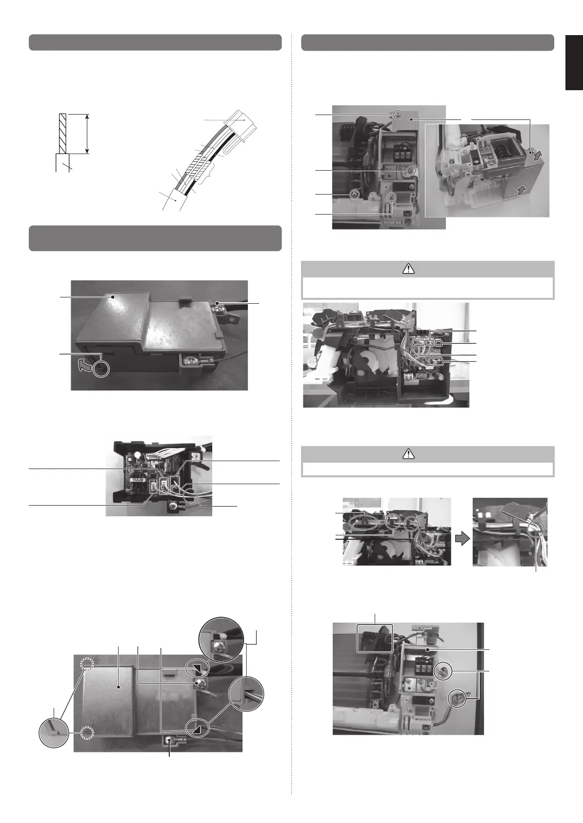
11.3.2. Removing control box
(1) Removethescrews(x4).(Usethesamescrewswheninstalling.)
(2) Pullthecontrolboxcovertowardsyouandremove.
(1)
(1)
(2)
(1)
(1)
(3) Removetheconnectors(x4).
• Removeandpulloffthelockatthesideoftheconnectorinsertionpart.
CAUTION
•Becarefulnottodamagethepartsontheboard.
Otherwise,itwillcausemalfunction.
Connectornumber:CN5*
Connectornumber:CN4*
Connectornumber:CN3*
Connectornumber:CN7*
*:Symbolindicatingthelocationprintedontheboard
(4) Removethewiresfromthethreefixtures.(Seethefigurebelow)
• LeavethethickgreenwireinfixtureCandremovetherestofthewires.
CAUTION
•Donotpullthewiresforcibly.Youmaydamagethem.
FixtureA
Before After
FixtureB
FixtureC
FixtureC
(5) Whilepullingthecontrolboxtowardsyou,removeintherightdirection.
• Donotremovethethermistor.
• Donotdamagetheterminalsontheremovedwires.
Thermistor
Controlbox
Terminals
11.1. Remote controller cable modication
(1) Useatooltocutofftheterminalontheendoftheremotecontrollercable,andthen
removetheinsulationfromthecutendofthecable.
(2) Connecttheremotecontrollercableandconnectingcable.
(suppliedwithwiredremotecontroller)
Important:Besuretosolderwirestoconnect.Besuretoinsulatetheconnection
betweenthewires.
Connectingcable
White
Red
White
Red
Black
Black
Insulated
connection
Remote
controllercable
Remote
controllercable
20mm
11.2. Installing wired remote controller terminal /
external connect kit terminal (sold separately)
(1) Removethescrewonthecontrolboxasshownonthetoprightofthefigurebelow.
(2) Releasebothbottomclaspsatthesidesinthedirectionofthearrowascircledin
thebottomleftofthefigurebelow.Pullandremovethecover.
(2)
(1)
Cover
(3) Connectthewiredremotecontrollerterminal/externalconnectkitterminal(sold
separately)tothespecifiedterminalontheboardasshownbelow.Pleaseconnect
totheconnectorwithnecessaryfunctionaccordingtotheactualusage.
(4) Afterconnectingeachterminal,threadthecablesthroughthenotchascircledon
thebottomrightofthefigurebelow.
(3) Controlinput(Operation/
StoporForcedstop)
connector
:CNA01(White)*
(3) Wiredremotecontroller
connector
:CNC01(White)*
*:Symbolindicatingthelocationprintedontheboard
(3) ErrorStatusoutput
connector
:CNB02(Black)*
(3) Operationstatus
outputconnector
:CNB01(White)*
(4)
(5)Installthecontrolboxcoverasshownbelow.
(Alignthecoverwiththeupperandlowerrightcornersasindicatedbythetriangular
symbolsonthefigure.
Inserttheclaspsonthecoverintobothsidesatthebottomofthetwodotted
circles.)
• Wheninstallingthecontrolboxcover,makesurethatthecablesarenotcaughtas
showninthedetailview.
(6)Installonescrew.
(7)Screwtheearthwireofwiredremotecontrollerasshowninthefigure.(AUSTRALIA
modelonly).
(7)
(5)
(5)(6)Cover
Detailview
9333005225_IM_2L.indb 7 10/12/2017 08:48:53
 Loading...